Difference between revisions of "Brushed DC Motor Theory"
m (→Motor Physics) |
m (→Motor Physics) |
||
| Line 17: | Line 17: | ||
|} |
|} |
||
You can easily find the direction of this force using the ''Right Hand Rule''. The ''Right Hand Rule'' states that if you point your right hand fingers along the direction of current, <math>I</math>, and curl them towards the direction of the magnetic flux, <math>B</math>, the direction of force is along the thumb. See the picture below. |
|||
[[image:Right Hand Rule.jpg|center|400px]] |
[[image:Right Hand Rule.jpg|center|400px]] |
||
Revision as of 17:51, 7 July 2006
Introduction
The specific type of motor we are addressing is the permanent magnet brushed DC motor (PMDC). These motors have two terminals. Applying a voltage across the terminals results in a proportional speed of the output shaft.
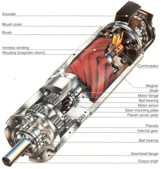
There are two pieces to the motor: 1) stator and 2) rotor. The stator includes the housing,, windings and brushes. The rotor consists of the output shaft, windings and commutators. The image below shows a cut-away view of a Maxon motor. Note this picture has a gearbox and encoder attached to the motor.
Motor Physics
The forces inside a motor that cause the rotor to rotate are called Lorentz Forces. If an electron is moving through an electric field, it experiences a force that is perpendicular to both the magnetic field and the direction it's moving. If we have a wire instead of a single electron, the wire experiences a force equal to
You can easily find the direction of this force using the Right Hand Rule. The Right Hand Rule states that if you point your right hand fingers along the direction of current, , and curl them towards the direction of the magnetic flux, , the direction of force is along the thumb. See the picture below.
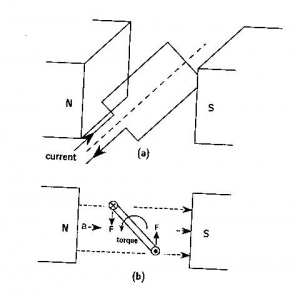
Now, imagine a loop of wire with some resistance is inserted between the two permanent magnets. The following diagrams show how the motor turns:
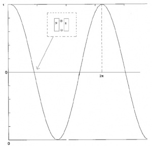
You might be able to notice that the direction of rotation is changing every half cycle. To keep it rotating in the same direction, we have to switch the current direction. The process of switching current is called commutation. To switch the direction of curent, we have to use brushes and commutators. Commutation can also be done electronically (Brushless motors) and a brushless motor usually has a longer life. The following diagram shows how brushes and commutators work.
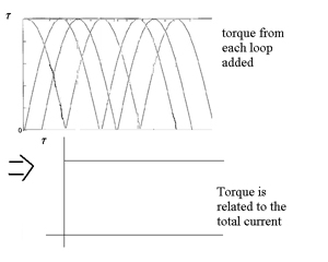
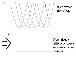
We could also have several commutators and loops. The total torque generated is the sum of all the torques from each of the loops added.
|
|
Equations
So, the torque is proportional to the current through the windings,
,
where is the torque, is the current, and is a constant. The wire coils have both a resistance, , and an inductance, . When the motor is turning, the current is switching, causing a voltage,
This voltage is known as the back-emf(electromotive force), . If the angular velocuty of the motor is , then
,
like a generator. This voltage, , is working against the voltage we apply across the terminals, and so,
,
where
which implies
.
The maximum or stall torque is the torque at which or
,
and the stall or starting current,
The no load speed,
,
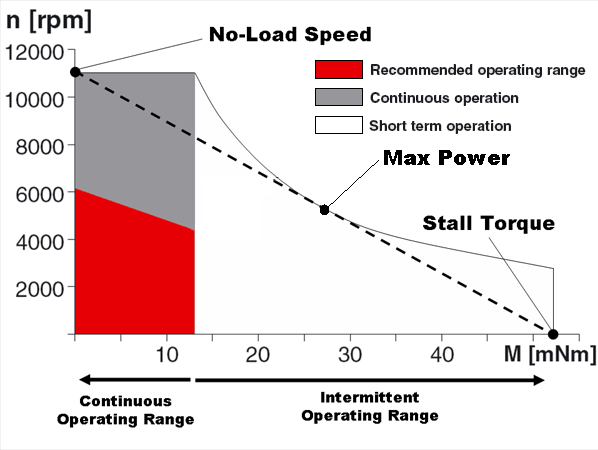
is the maximum speed the motor can run. Given a constant voltage, the motor will settle at a constant speed, just like a terminal velocity. If we plot
,
we can get a linear speed-torque curve. This line is the dashed line shown in the dc motor speed-torque graph for a Maxon brushed DC motor shown below:
Units
Here are the different units for the torque, current and voltage
| Parameter | Symbol | Common Units |
|---|---|---|
| Torque | Nm (=kgm/s^2*m), kgfm(=9.8 times Nm), gfcm, mNm, etc | |
| Current | Amperes(Amps), mA | |
| Voltage | Volts | |
| Mechanical Power | 1 Nm/sec = 1 watt | |
| Electrical Power | 1 volt*amp = 1 watt |
References
- Carl R. Nave, "DC Motors," http://hyperphysics.phy-astr.gsu.edu/hbase/magnetic/motdc.html
