Difference between revisions of "Logic Gates"
| Line 4: | Line 4: | ||
==AND Gate== |
==AND Gate== |
||
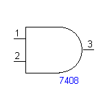
The symbol for the '''AND gate''':[[Image:AND_gate_symbol.gif]] |
The symbol for the '''AND gate''':[[Image:AND_gate_symbol.gif]] |
||
Pins 1 and 2 are inputs, and pin 3 is the output. |
|||
The AND gate will will output ''1'' if both inputs are also ''1''. |
The AND gate will will output ''1'' if both inputs are also ''1''. |
||
Latest revision as of 16:39, 29 June 2006
Digital circuits use Boolean logic to perform operations. Everything is in either one of two states: 1 (true) or 0 (false). Depending on your hardware, 1 usually corresponds to a high voltage and 0 corresponds to a low voltage.
AND Gate
Pins 1 and 2 are inputs, and pin 3 is the output.
The AND gate will will output 1 if both inputs are also 1.
| Inputs | Output | |
|---|---|---|
| 0 | 0 | 0 |
| 0 | 1 | 0 |
| 1 | 0 | 0 |
| 1 | 1 | 1 |
OR Gate
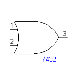
The OR gate will output 1 if any one or both of its inputs are 1.
| Inputs | Output | |
|---|---|---|
| 0 | 0 | 0 |
| 0 | 1 | 1 |
| 1 | 0 | 1 |
| 1 | 1 | 1 |
Inverter (NOT) Gate
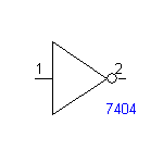
This is a NOT gate, but in digital circuits it is usually called an inverter.
The OR gate will output 1 if its single input is 0.
| Input | Output |
|---|---|
| 0 | 1 |
| 1 | 0 |
NAND Gate
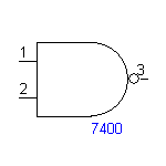
The NAND gate is simply an AND gate with an inverter at the output. Notice the "bubble" at the output node of the symbol; this bubble indicates an inverted output.
| Inputs | Output | |
|---|---|---|
| 0 | 0 | 1 |
| 0 | 1 | 1 |
| 1 | 0 | 1 |
| 1 | 1 | 0 |
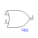
NOR Gate
Similarly, the NOR gate is just an inverted OR gate. t will output 1 if neither of its inputs are 1.
| Inputs | Output | |
|---|---|---|
| 0 | 0 | 1 |
| 0 | 1 | 0 |
| 1 | 0 | 0 |
| 1 | 1 | 0 |
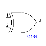
XOR
The XOR (Exclusive OR) gate will output 1 if either of its inputs are 1, but not if both of its inputs are 1.
| Inputs | Output | |
|---|---|---|
| 0 | 0 | 0 |
| 0 | 1 | 1 |
| 1 | 0 | 1 |
| 1 | 1 | 0 |
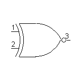
XNOR
The XNOR gate is an inverted NOT gate; it will output 1 if neither of its inputs are 1, or if both of its inputs are 1.
| Inputs | Output | |
|---|---|---|
| 0 | 0 | 1 |
| 0 | 1 | 0 |
| 1 | 0 | 0 |
| 1 | 1 | 1 |
