Difference between revisions of "Strain Gauge"
m |
m |
||
| Line 1: | Line 1: | ||
===Overview=== |
===Overview=== |
||
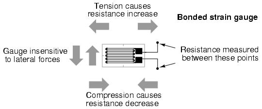
Strain gauges are simple sensors that can be used to measure forces. They consist peice of conducting material that changes resistance as it is stretched in a given direction. The diagram below shows this: |
|||
[[image:strain gauge.jpg]] |
|||
===Circuitry=== |
===Circuitry=== |
||
Typically, the change in resistance of the strain gauge is very small. In order to accurately measure this small change, special circuitry is needed. For this, a ''wheatstone bridge'' configuration is usually employed. There are variants on how this circuit can be arranged; two are presented below. |
|||
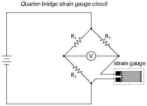
The first configuration is the simplest method. The wheatstone bridge measures small imbalances in the resistances. Here it is comparing the strain gauge resistance to <math>R_3</math>, which has a resistance equal to the resistance of the unstretched strain gauge. The other two resistors should have similar values. |
|||
[[image:simple strain guage circuit.jpg]] |
|||
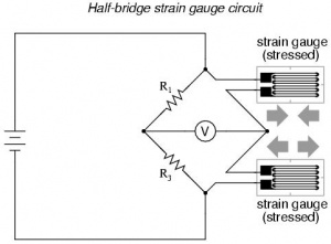
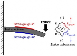
Next is a more advanced circuit used for measuring strain in both directions. Two strain gauges are used, and must be positioned carefully, as shown in the second figure. |
|||
{| |
|||
|- |
|||
| [[image:advanced strain gauge circuit.jpg|300px]] |
|||
| [[image:advanced strain gauge attachment.jpg|300px]] |
|||
|} |
|||
Revision as of 09:56, 27 June 2006
Overview
Strain gauges are simple sensors that can be used to measure forces. They consist peice of conducting material that changes resistance as it is stretched in a given direction. The diagram below shows this:
Circuitry
Typically, the change in resistance of the strain gauge is very small. In order to accurately measure this small change, special circuitry is needed. For this, a wheatstone bridge configuration is usually employed. There are variants on how this circuit can be arranged; two are presented below.
The first configuration is the simplest method. The wheatstone bridge measures small imbalances in the resistances. Here it is comparing the strain gauge resistance to , which has a resistance equal to the resistance of the unstretched strain gauge. The other two resistors should have similar values.
Next is a more advanced circuit used for measuring strain in both directions. Two strain gauges are used, and must be positioned carefully, as shown in the second figure.

|

|


