Difference between revisions of "PIC32MX: Sinusoidal Analog Output"
Andrew Long (talk | contribs) |
LawrenceChen (talk | contribs) |
||
| Line 1: | Line 1: | ||
The PIC32 is actually incapable of directly creating an analog output. Instead, the PIC32 can perform pulse width modulation (PWM) to create an average analog output. At a given frequency, PWM varies the time that the output pin is on (output is 3.3V) to create the duty cycle which can simulate voltages between 0V and 3.3V. For example, if the duty cycle is 50%, the PIC32 holds the pin at 3.3V 50% of the time and 0V for the other 50%. The average output voltage is then 1.65V. If the pin is connected to an external RC circuit, the PWM can be integrated. By varying the duty cycle sinusoidally, the output with an RC circuit can resemble a sinusoid. Thus, to create the sinusoidal output, a sinusoidal wave must be divided into a discrete number of points. These points can then be converted to a list of duty cycles to represent the sinusoid. |
The PIC32 is actually incapable of directly creating an analog output. Instead, the PIC32 can perform pulse width modulation (PWM) to create an average analog output. At a given frequency, PWM varies the time that the output pin is on (output is 3.3V) to create the duty cycle which can simulate voltages between 0V and 3.3V. For example, if the duty cycle is 50%, the PIC32 holds the pin at 3.3V 50% of the time and 0V for the other 50%. The average output voltage is then 1.65V. If the pin is connected to an external RC circuit, the PWM can be integrated. By varying the duty cycle sinusoidally, the output with an RC circuit can resemble a sinusoid. Thus, to create the sinusoidal output, a sinusoidal wave must be divided into a discrete number of points. These points can then be converted to a list of duty cycles to represent the sinusoid. |
||
The three most important parameters in creating the sinusoidal analog output are the |
The three most important parameters in creating the sinusoidal analog output are the the number of points per period, the RC time constant, and the sinusoid frequency. The combination of the cutoff frequency and the points per period helps tell the PIC when to change the duty cycle. The RC constant of an external RC circuit is important in creating smooth and accurate curves and in improving the quality of the output signal. |
||
The code for the analog output will first generate a lookup table. This table contains values for the specific duty cycles and will generate the number of duty cycles based on the number of points specified by the user. After generating the table, the code goes through a loop which tells the board to output the appropriate PWM corresponding to the duty cycle in the lookup table at each time step. By looping through the duty cycles at the same time intervals, the output voltage is varied to match that of a sine wave. The external RC circuit acts as a buffer to store these voltages to smooth the final output voltage to yield the sine wave. Without this external RC circuit, the output would only be a series of pulses matching the duty cycle at a given time. |
The code for the analog output will first generate a lookup table. This table contains values for the specific duty cycles and will generate the number of duty cycles based on the number of points specified by the user. After generating the table, the code goes through a loop which tells the board to output the appropriate PWM corresponding to the duty cycle in the lookup table at each time step. By looping through the duty cycles at the same time intervals, the output voltage is varied to match that of a sine wave. The external RC circuit acts as a buffer to store these voltages to smooth the final output voltage to yield the sine wave. Without this external RC circuit, the output would only be a series of pulses matching the duty cycle at a given time. |
||
The equation governing the sine wave is |
|||
| ⚫ | |||
| ⚫ | |||
The equation governing the duty cycle is |
|||
<math>duty cycle = \frac{MAX\_DUTY}{2y} + \frac{MAX\_DUTY}{2}</math> |
|||
where the <math>MAX\_DUTY</math> is determined by the frequency of the PWM |
|||
The examples below have a PWM frequency of 20kHz. |
The examples below have a PWM frequency of 20kHz. |
||
| Line 12: | Line 20: | ||
__TOC__ |
__TOC__ |
||
| ⚫ | |||
To choose the cut-off frequency of the external RC circuit, you use the equation |
|||
| ⚫ | |||
| ⚫ | |||
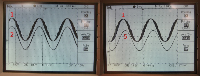
If the chosen cut-off frequency is too high (RC constant is too low), then the output signal will be very noisy and not as clear. If the chosen frequency is too low (RC constant is too high), then the final output signal through the RC circuit will be more likely to have a decreased amplitude, thus you'll only get a limited range of voltages. |
|||
Whether or not the cut-off frequency is too high or too low depends on the frequency at which the board is outputting the PWM voltage. So as the output frequency of the board increases and approaches the cutoff frequency (thus the cutoff frequency would be too low), the amplitude of the final analog output voltage will be decreased. |
|||
[[Image:RCcompare.jpg|center|frame|The sine waves were generated at 25Hz with 100 points. The sine wave labeled 1 was generated with an RC constant of 4.7 x 10^-5, the sine wave labeled 2 was generated using an RC constant 2.2 x 10^-4 and the sine wave labeled 5 was generated using an RC constant 4.7 x 10^-3. Notice that sine waves 1 and 2 have close to the same amplitudes (around 3.3V) but sine wave 1 has a very messy signal, thus the cutoff frequency would be too high. Also notice that sine wave 5 only has a maximum amplitude of 3.0V, thus the cutoff frequency would be too low.]] |
|||
==Number of Points Per Period== |
==Number of Points Per Period== |
||
| Line 40: | Line 35: | ||
[[Image:RCcompare.jpg|center|frame|The sine waves were generated at 25Hz with 100 points. The sine wave labeled 1 was generated with an RC constant of 4.7 x 10^-5, the sine wave labeled 2 was generated using an RC constant 2.2 x 10^-4 and the sine wave labeled 5 was generated using an RC constant 4.7 x 10^-3. Notice that sine waves 1 and 2 are almost synchronized, but sine waves 1 and 5 have a time offset caused by the phase lag from the high RC constant.]] |
[[Image:RCcompare.jpg|center|frame|The sine waves were generated at 25Hz with 100 points. The sine wave labeled 1 was generated with an RC constant of 4.7 x 10^-5, the sine wave labeled 2 was generated using an RC constant 2.2 x 10^-4 and the sine wave labeled 5 was generated using an RC constant 4.7 x 10^-3. Notice that sine waves 1 and 2 are almost synchronized, but sine waves 1 and 5 have a time offset caused by the phase lag from the high RC constant.]] |
||
| ⚫ | |||
==Sample Code== |
==Sample Code== |
||
Revision as of 21:58, 8 May 2010
The PIC32 is actually incapable of directly creating an analog output. Instead, the PIC32 can perform pulse width modulation (PWM) to create an average analog output. At a given frequency, PWM varies the time that the output pin is on (output is 3.3V) to create the duty cycle which can simulate voltages between 0V and 3.3V. For example, if the duty cycle is 50%, the PIC32 holds the pin at 3.3V 50% of the time and 0V for the other 50%. The average output voltage is then 1.65V. If the pin is connected to an external RC circuit, the PWM can be integrated. By varying the duty cycle sinusoidally, the output with an RC circuit can resemble a sinusoid. Thus, to create the sinusoidal output, a sinusoidal wave must be divided into a discrete number of points. These points can then be converted to a list of duty cycles to represent the sinusoid.
The three most important parameters in creating the sinusoidal analog output are the the number of points per period, the RC time constant, and the sinusoid frequency. The combination of the cutoff frequency and the points per period helps tell the PIC when to change the duty cycle. The RC constant of an external RC circuit is important in creating smooth and accurate curves and in improving the quality of the output signal.
The code for the analog output will first generate a lookup table. This table contains values for the specific duty cycles and will generate the number of duty cycles based on the number of points specified by the user. After generating the table, the code goes through a loop which tells the board to output the appropriate PWM corresponding to the duty cycle in the lookup table at each time step. By looping through the duty cycles at the same time intervals, the output voltage is varied to match that of a sine wave. The external RC circuit acts as a buffer to store these voltages to smooth the final output voltage to yield the sine wave. Without this external RC circuit, the output would only be a series of pulses matching the duty cycle at a given time.
The equation governing the sine wave is
Failed to parse (MathML with SVG or PNG fallback (recommended for modern browsers and accessibility tools): Invalid response ("Math extension cannot connect to Restbase.") from server "https://wikimedia.org/api/rest_v1/":): {\displaystyle y=A*sin(\frac{2 \pi}{N*i})}
where Failed to parse (MathML with SVG or PNG fallback (recommended for modern browsers and accessibility tools): Invalid response ("Math extension cannot connect to Restbase.") from server "https://wikimedia.org/api/rest_v1/":): {\displaystyle A}
is the amplitude of the sinusoid, Failed to parse (MathML with SVG or PNG fallback (recommended for modern browsers and accessibility tools): Invalid response ("Math extension cannot connect to Restbase.") from server "https://wikimedia.org/api/rest_v1/":): {\displaystyle N}
is the number of points and is the index.
The equation governing the duty cycle is Failed to parse (MathML with SVG or PNG fallback (recommended for modern browsers and accessibility tools): Invalid response ("Math extension cannot connect to Restbase.") from server "https://wikimedia.org/api/rest_v1/":): {\displaystyle duty cycle = \frac{MAX\_DUTY}{2y} + \frac{MAX\_DUTY}{2}} where the Failed to parse (MathML with SVG or PNG fallback (recommended for modern browsers and accessibility tools): Invalid response ("Math extension cannot connect to Restbase.") from server "https://wikimedia.org/api/rest_v1/":): {\displaystyle MAX\_DUTY} is determined by the frequency of the PWM
The examples below have a PWM frequency of 20kHz.
Number of Points Per Period
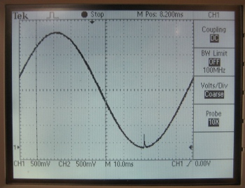
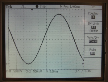
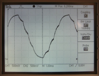
Selecting the number of points to use to generate the sine wave is important because choosing too few will result in a very rough sine wave. When the number of points is too low, you can actually see multiple RC charging graphs between each point. However, if we choose too many points, a peak appears at what should be 0V on the sine wave. To prevent this peek from occurring, one could insert an “if” statement in the lookup table generation loop that replaces all of the occurring 0’s into 1’s. Inclusion of the if statement would result in no true 0V output for that particular output. The ideal number of points for 25Hz is around 200 points.
RC Time Constant
The RC time constant plays a big role in creating the sine wave. By increasing the RC constant, the quality of the output signal is increased, where "quality" refers to the width of the output signals. Despite having such advantages, a larger RC constant will result in a phase lag which causes a delay between the output of the PIC and the output from the whole circuit.

Sine Frequency
Sample Code
This sample code creates an analog output on PINS D0 and D1 using 200 points at a sine frequency of 25Hz.
/******************************************************
Sinusoidal Output
*/

#include "HardwareProfile.h"
#include "math.h"

#define DESIRED_BAUDRATE    	(9600)      // The desired BaudRate
#define NUM_POINTS_PER_PERIOD		200

int timeStep = 0;
int LookupTable[NUM_POINTS_PER_PERIOD];

int main(void)
{
	int sineFreq = 25;
	int interruptFreq = NUM_POINTS_PER_PERIOD * sineFreq;
	int periodValue = (SYS_FREQ / interruptFreq / 1) - 1;

	// Configure the proper PB frequency and the number of wait states
	SYSTEMConfigPerformance(SYS_FREQ);

	// Allow vector interrupts
	INTEnableSystemMultiVectoredInt();

	// init OC1 module, on pin D0
	OpenOC1( OC_ON | OC_TIMER2_SRC | OC_PWM_FAULT_PIN_DISABLE, 0, 0);
	// init OC1 module, on pin D1
	OpenOC2( OC_ON | OC_TIMER2_SRC | OC_PWM_FAULT_PIN_DISABLE, 0, 0);

	// init Timer2 mode and period (PR2) // produces 20kHz PWM
	OpenTimer2( T2_ON | T2_PS_1_1 | T2_SOURCE_INT, 3999);


	int i;
	for (i = 0; i < NUM_POINTS_PER_PERIOD; i++)
	{
		LookupTable[i] = (int)(3999/2 * sin(2*M_PI/NUM_POINTS_PER_PERIOD*i)+ 3999/2);
	}


	// init Timer3 for Sinusoid Interrupt
	// Assume Prescalar is 2
	// Need to verify that SYS_FREQ / sineFreq / numPoints < 65534
	OpenTimer3( T3_ON | T3_PS_1_1 | T3_SOURCE_INT, periodValue);

	mT3SetIntPriority( 7); 	// set Timer3 Interrupt Priority
	mT3ClearIntFlag(); 		// clear interrupt flag
	mT3IntEnable( 1);		// enable timer3 interrupts

	// this will store the string for the LCD
	char LCDbuffer[33];

	while(1)
	{
		// Timer 3 ISR takes care of the code
	}

	CloseOC1();

}//end main

// interrput code
void __ISR( _TIMER_3_VECTOR, ipl7) T3Interrupt( void)
{
	if (++timeStep >= NUM_POINTS_PER_PERIOD)
	{
		timeStep = 0;
	}

	SetDCOC1PWM(LookupTable[timeStep]);
	SetDCOC2PWM(LookupTable[timeStep]);

	// clear interrupt flag and exit
	mT3ClearIntFlag();
} // T3 Interrupt


