Difference between revisions of "PIC32MX: Sinusoidal Analog Output"
Andrew Long (talk | contribs) |
LawrenceChen (talk | contribs) |
||
| Line 27: | Line 27: | ||
==RC Time Constant== |
==RC Time Constant== |
||
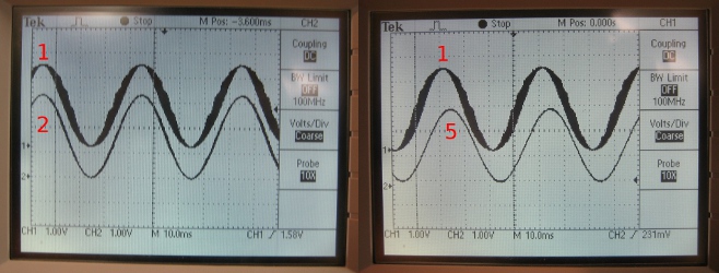
The RC time constant plays a big role in creating the sine wave. By increasing the RC constant, the quality of the output signal is increased, where "quality" refers to the width of the output signals. Despite having such advantages, a larger RC constant will result in a phase lag which causes a delay between the output of the PIC and the output from the whole circuit. |
|||
Explain that a large RC time constant smooths the plot but introduces a phase lag. |
|||
[[Image:RCcompare.jpg|center|frame|The sine waves were generated at 25Hz with 100 points. The sine wave labeled 1 was generated with an RC constant of 4.7 x 10^-5, the sine wave labeled 2 was generated using an RC constant 2.2 x 10^-4 and the sine wave labeled 5 was generated using an RC constant 4.7 x 10^-3. ]] |
|||
Show the pictures you provided in the presentation. |
|||
==Sample Code== |
==Sample Code== |
||
Revision as of 20:11, 1 May 2010
Overview:
How do we obtain analog output? ie PWM (brief description)
How do we get sinusoidal output? ie divide up sinusoid into N points, scale duty cycle accordingly
General discussion about how cutoff frequency, number of points period (N) and the RC time constant matter.
State that the examples here have PWM at 20kHz.
Cutoff Frequency
How to choose cut-off frequency -- what is the equation?
Show picture if you choose your frequency to high and if you choose your frequency to low.
Say something about how the amplitude decreases with high frequency
Number of Points Per Period
Show Pictures of number of points to small - discuss that you see the capacitor charging
Show picture of good number of points
RC Time Constant
The RC time constant plays a big role in creating the sine wave. By increasing the RC constant, the quality of the output signal is increased, where "quality" refers to the width of the output signals. Despite having such advantages, a larger RC constant will result in a phase lag which causes a delay between the output of the PIC and the output from the whole circuit.
Sample Code
Include your sample code (this may need cleaned up a bit).
To make a box around the code, put a 'space' in front of each line.
