Difference between revisions of "PIC32MX: Parallel LCD"
NickMarchuk (talk | contribs) |
NickMarchuk (talk | contribs) |
||
| Line 105: | Line 105: | ||
== Files and Example Code == |
== Files and Example Code == |
||
Include the following h and c files to your project: |
Include the following h and c files to your project: [[Media:LCD_NU32.zip|h and c files]] |
||
'''LCD.h''' |
'''LCD.h''' |
||
Revision as of 13:04, 11 January 2010
Parallel LCD
The popular HD44780 (and compatible chipsets) can be interfaced to the NU32 PIC32 board using 6 pins for easy character output to an LCD. This can be highly useful in either debugging or generating a more complex user interface for a PIC (or other microcontroller)-based device.
This implementation of an HD44780 LCD uses only 6 I/O on the PIC, but is not optimized for speed. If you need more efficient output, more pins can be used for communication, and this code would need to be altered slightly, but for debugging purposes start with this implementation.
LCD Hookup
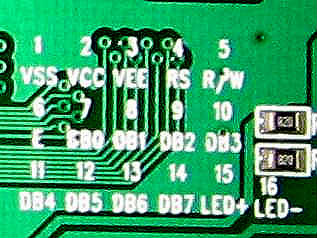
First you will need to locate the appropriate datasheet for the actual LCD you are using. What you will want to look up in there is the arrangement of connectors on the top-left of the display, and their names so that you can appropriately match the right connectors with the correct pins on the microcontroller, and in turn with the correct software identifiers for those connections. An example of one such pin arrangement is below.
 |
|
Your controller may differ from this one. Occasionally even if you've got the right datasheet these pin numbers can be backwards. If it has a backlight, try powering that up first and ensure that works.
Next, you'll need to wire up the LCD for power, and the connections with the pic.
| LCD Pin | PIC Pin |
| 1 - VSS | GND |
| 2 - VCC | +5V |
| 3 - VEE | ~1V |
| 4 - RS | D4 |
| 5 - R/W | GND |
| 6 - E | D10 |
| 7 - DB0 | NC |
| 8 - DB1 | NC |
| 9 - DB2 | NC |
| 10 - DB3 | NC |
| 11 - DB4 | D0 |
| 12 - DB5 | D1 |
| 13 - DB6 | D2 |
| 14 - DB7 | D3 |
| 15 - LED+ | +3.3V |
| 16 - LED- | GND |
The VEE pin on the LCD sets the contrast of the characters on the LCD. Create with a voltage around 1V using a 10k pot to get a nice contrast, or hook it to GND through a 1.5kOhm resistor, which also seems to work well.
If you power the LCD but do not send it any commands, the top row should fill with boxes. Use this to set your contrast and check that your LCD works.
The NU32 board is based on 3.3V logical outputs, which works fine for most LCDs.
LCD Commands
In the main.c file, before the main while loop, you must initialize the LCD
lcd_init(); // Always call this first
The basic command used to write to the LCD is
// write Hello World
putsLCD("Hello World");
You can directly set the cursor position by using
// move the cursor to the second line, 3rd character position
lcd_gotoxy(3, 2)
Remember the LCD can display 16 x 2 characters.
Special characters can also be used to set the cursor position
// clear the screen and put the cursor in the top left
putsLCD("\f");

// put the cursor in the bottom right
putsLCD("\n");
Write the contents of an integer using
// write the value of int counter
putsLCD("\fCounter = %f", counter); //currently not supported NDM 1/4/10
Files and Example Code
Include the following h and c files to your project: h and c files
LCD.h
LCD.c
To test these commands, here is a basic main file that writes some text: main.c