Difference between revisions of "Characterizing the response of a solenoid"
| Line 39: | Line 39: | ||
The upper trace is the accelerometer, the lower trace is the voltage across the solenoid. On the accelerometer trace 0g corresponds with 2.5V, +18g is 0V and -18g is 5V. |
The upper trace is the accelerometer, the lower trace is the voltage across the solenoid. On the accelerometer trace 0g corresponds with 2.5V, +18g is 0V and -18g is 5V. |
||
| ⚫ | |||
=== Very Low Frequency (<10Hz) Response === |
|||
| ⚫ | |||
'''Region A-B-C-D''' |
'''Region A-B-C-D''' |
||
| Line 52: | Line 54: | ||
<br clear="all"> |
<br clear="all"> |
||
===Low Frequency (<100 Hz) Response=== |
|||
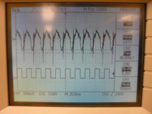
These scope traces show the erratic vibrations at low frequencies. At these frequencies the solenoid plunger hits both end stops. The erratic acceleration is due to the spring becoming completely unloaded as the plunger exits the solenoid and the subsequent recontact between the plunger and spring. |
These scope traces show the erratic vibrations at low frequencies. At these frequencies the solenoid plunger hits both end stops. The erratic acceleration is due to the spring becoming completely unloaded as the plunger exits the solenoid and the subsequent recontact between the plunger and spring. |
||
| Line 60: | Line 64: | ||
<br clear="all"> |
<br clear="all"> |
||
===Response to Varying Driving Duty Cycle=== |
|||
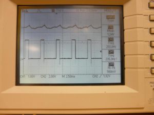
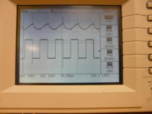
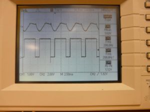
These scope traces show the effects of varying the duty cycle with constant amplitude (24V) and frequency (200Hz). At this higher frequency the plunger retains contact with the return spring and does not hit either end stop. Note that at 75% duty cycle the acceleration profile approaches a square wave. |
These scope traces show the effects of varying the duty cycle with constant amplitude (24V) and frequency (200Hz). At this higher frequency the plunger retains contact with the return spring and does not hit either end stop. Note that at 75% duty cycle the acceleration profile approaches a square wave. |
||
| Line 68: | Line 74: | ||
<br clear="all"> |
<br clear="all"> |
||
===Response to Varying Driving Amplitude=== |
|||
These scope traces show the effects of varying driving amplitude at constant frequency (300Hz) and duty cycle (50%) |
These scope traces show the effects of varying driving amplitude at constant frequency (300Hz) and duty cycle (50%) |
||
| Line 76: | Line 84: | ||
<br clear="all"> |
<br clear="all"> |
||
===Resonance (~20Hz)=== |
|||
[[Image:Resonance.JPG|right|thumb|500px|Resonance]] |
[[Image:Resonance.JPG|right|thumb|500px|Resonance]] |
||
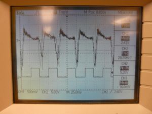
Resonance was observed at 20Hz resulting in very high downward (negative) accelerations indicating contact between the plunger and the solenoid stop. From A to B the plunger is accelerating upward with a negative jerk. Since the solenoid is unpowered in this region this indicates that gravity is taking control of the plunger after losing contact with the spring. The acceleration from B-C rapidly decays to baseline because the square wave voltage across the solenoid goes high and the solenoid pulls the plunger downward, compressing the spring. Region C-D occurs under a powered solenoid which accelerates the plunger downward with positive jerk. The ~11g reading (1.5V swing) at D indicates the plunger hits the lower stop. The rebound off the lower stop causes the spring to decompress quickly over D-E, propelling the plunger beyond the spring. |
Resonance was observed at 20Hz resulting in very high downward (negative) accelerations indicating contact between the plunger and the solenoid stop. From A to B the plunger is accelerating upward with a negative jerk. Since the solenoid is unpowered in this region this indicates that gravity is taking control of the plunger after losing contact with the spring. The acceleration from B-C rapidly decays to baseline because the square wave voltage across the solenoid goes high and the solenoid pulls the plunger downward, compressing the spring. Region C-D occurs under a powered solenoid which accelerates the plunger downward with positive jerk. The ~11g reading (1.5V swing) at D indicates the plunger hits the lower stop. The rebound off the lower stop causes the spring to decompress quickly over D-E, propelling the plunger beyond the spring. |
||
<br clear="all"> |
<br clear="all"> |
||
===Response of Driving Near Resonance=== |
|||
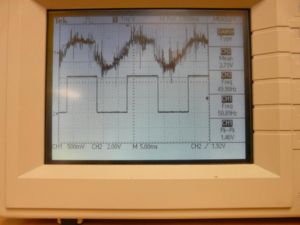
These scope traces show the response just before, just after, and at the resonant frequency of 20Hz |
These scope traces show the response just before, just after, and at the resonant frequency of 20Hz |
||
Revision as of 10:13, 12 February 2009
Original Assignment
Your job is to characterize the response of a solenoid to on-off pulsed forcing. The solenoid should be equipped with a return spring so that the solenoid returns to a home position when the coil is de-energized.
You should provide the user with the ability to control three parameters of the on-off pulsed forcing: the frequency of the on-off pulsed forcing, the duty cycle, and the amplitude (the voltage or current applied to the coil when it is energized). You will mount an accelerometer on the shaft of the solenoid and use an oscilloscope to simultaneously look at the control voltage to the solenoid and the acceleration of the solenoid. Try frequencies from 10 Hz to hundreds of Hz. For what frequencies, duty cycles, and amplitudes does the solenoid shaft hit stops, and for what values do you get approximate square wave acceleration profiles? Summarize your results in text and post clear images of the oscilloscope for a few representative choices.
Note: your PIC may not be involved in this assignment at all. You could use a function generator to generate the frequency and duty cycle you want, and use the amplitude to (perhaps) control a transistor operating in the linear regime to deliver different amounts of current to the solenoid. It may make sense to always energize the coil a little bit, even in the "off" state, so that the return spring is always in a bit of tension.
Overview
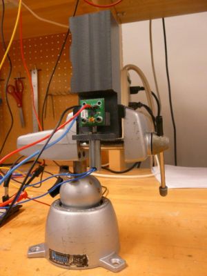
The objective of this experiment was to understand the behavior of a solenoid at various input frequencies, duty cycles and voltages. The PIC was not needed for this experiment at all because independent adjustment of all three parameters was capable using the bench top function generator and power supply. We used an accelerometer attached to the solenoid plunger and a small return spring to return the plunger to its original position when the solenoid was unpowered. By simultaneously tracking the on-off pulsed forcing of the solenoid and the acceleration responses of the plunger we were able to interpret our results.
Circuit
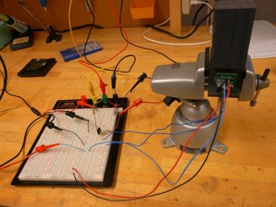
The bench top function generator was able to drive the solenoid at different frequencies and with different PWM signals, but unable to provide enough current to move the plunger with much force. Therefore we used a single MOSFET driving circuit with the function generator providing the gate voltage and switching the solenoid on and off using the separate power supply which was able to give us the needed current to get a noticeable response. Because of the inductance of the solenoid coil and the fast switching on and off, a flyback diode was used.
The ADXL321EB accelerometer evaluation board (spec sheet here [[1]]) had three simple pin connections as well. One pin for +5V, one for ground, and because of the orientation was used for the evaluation board, one to track the Y-axis acceleration.
Oscilloscope Graphs
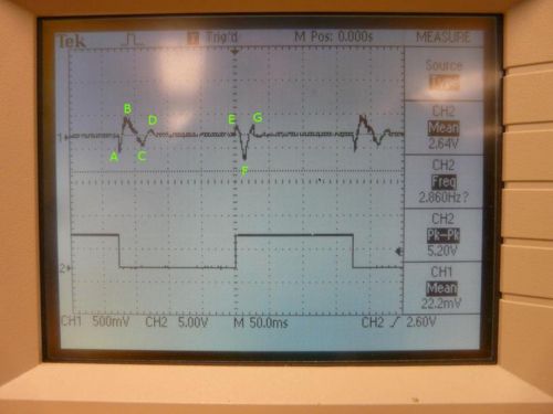
The upper trace is the accelerometer, the lower trace is the voltage across the solenoid. On the accelerometer trace 0g corresponds with 2.5V, +18g is 0V and -18g is 5V.
Very Low Frequency (<10Hz) Response
Region A-B-C-D The accelerometer reading near A indicates a downward acceleration. This coincides the falling edge of the square wave, and the solenoid becomes unpowered which indicates some unusual effect.
The region above the baseline at B indicates an upward acceleration caused by the return spring. The subsequent oscillation from B-C-D is typical damped oscillatory motion. Since the solenoid is unpowered in this region the result makes sense.
Region E-F-G Since E coincides with the rising edge of the square wave and the solenoid is powered the upward acceleration at E is also unexplained. The region E-F which shows a downward acceleration is consistent with the solenoid pulling the plunger down with a positive jerk. At point F, maximum downward acceleration the return spring is compressed enough to induce negative jerk. The region near G of upward acceleration (above baseline) is the result of the plunger overshooting equilibrium between the spring compression and the solenoid until the solenoid can retake control and stop the oscillation.
Low Frequency (<100 Hz) Response
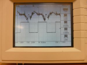
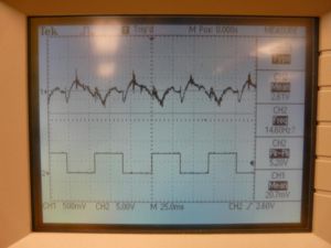
These scope traces show the erratic vibrations at low frequencies. At these frequencies the solenoid plunger hits both end stops. The erratic acceleration is due to the spring becoming completely unloaded as the plunger exits the solenoid and the subsequent recontact between the plunger and spring.
Response to Varying Driving Duty Cycle
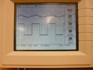
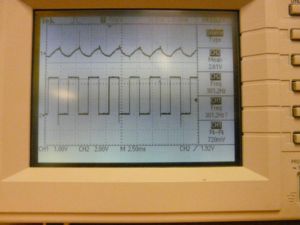
These scope traces show the effects of varying the duty cycle with constant amplitude (24V) and frequency (200Hz). At this higher frequency the plunger retains contact with the return spring and does not hit either end stop. Note that at 75% duty cycle the acceleration profile approaches a square wave.
Response to Varying Driving Amplitude
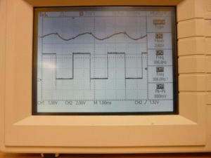
These scope traces show the effects of varying driving amplitude at constant frequency (300Hz) and duty cycle (50%)
Resonance (~20Hz)
Resonance was observed at 20Hz resulting in very high downward (negative) accelerations indicating contact between the plunger and the solenoid stop. From A to B the plunger is accelerating upward with a negative jerk. Since the solenoid is unpowered in this region this indicates that gravity is taking control of the plunger after losing contact with the spring. The acceleration from B-C rapidly decays to baseline because the square wave voltage across the solenoid goes high and the solenoid pulls the plunger downward, compressing the spring. Region C-D occurs under a powered solenoid which accelerates the plunger downward with positive jerk. The ~11g reading (1.5V swing) at D indicates the plunger hits the lower stop. The rebound off the lower stop causes the spring to decompress quickly over D-E, propelling the plunger beyond the spring.
Response of Driving Near Resonance
These scope traces show the response just before, just after, and at the resonant frequency of 20Hz
