Difference between revisions of "SPI communication between PICs"
| Line 67: | Line 67: | ||
== Code (Code mentioned on this page does NOT work when tried with the PIC18F4520) == |
== Code (Code mentioned on this page does NOT work when tried with the PIC18F4520) == |
||
<b>Hardware SPI</b> |
|||
Hardware SPI uses builtin hardware in the PIC18f4520 to send and receive SPI signals. First both master and slave must call the spi_setup() function. Then the master can send data with spi_write() and the slave can read with spi_read(). When using hardware SPI the slave will only listen to incoming data if the slave-select pin RA5 is pulled low. |
|||
<pre> |
<pre> |
||
| Line 73: | Line 76: | ||
software spi. This code does not work on PIC18F4520 and will require more experimentation. This is the code that |
software spi. This code does not work on PIC18F4520 and will require more experimentation. This is the code that |
||
looks most promising to start with from our review of codes on the internet for hardware SPI*/ |
looks most promising to start with from our review of codes on the internet for hardware SPI*/ |
||
/* For hardware spi, library functions such as spi_setup(), spi_read() and spi_write() can be used */ |
|||
/* For software spi, spi_xfer() can be used alongwith the #use spi directive*/ |
|||
/* We are not entirely sure if an output pin of the master should be connected to the SS pin (A5 for PIC18f4520) |
|||
of the slave and so we have commented out code that should be included if an output pin (PIN_D0 in this case) of |
|||
the master is connected to the SS pin of the slave/ |
|||
#include <18f4520.h> |
#include <18f4520.h> |
||
#fuses HS |
#fuses HS,NOLVP,NOWDT,NOPROTECT |
||
#use delay(clock=20000000) |
#use delay(clock=20000000) |
||
| Line 89: | Line 86: | ||
int value_read; // to be read from spi |
int value_read; // to be read from spi |
||
//it seems that the PIC does not generate proper output pulses in H_TO_L mode |
|||
//we had better success in L_TO_H mode |
|||
setup_spi(SPI_MASTER|SPI_H_TO_L|SPI_CLK_DIV_16); // sets the PIC as a master which generates the clock signal, a slower clock can be generated by changing 16 to 64 |
setup_spi(SPI_MASTER|SPI_H_TO_L|SPI_CLK_DIV_16); // sets the PIC as a master which generates the clock signal, a slower clock can be generated by changing 16 to 64 |
||
| Line 154: | Line 153: | ||
/* WATCH OUT FOR UPDATES */ |
/* WATCH OUT FOR UPDATES */ |
||
</pre> |
</pre> |
||
<b>Software SPI</b> |
|||
Below is some software SPI example code. Software SPI is enabled by the "#use spi" directive and, while slower than hardware SPI, can use any port as input or output. See the CCS compiler manual for more information on the "#use spi" directive options. |
|||
This code does not work either, though we can see on the oscilloscope that correct clock pulses and data pulses are being sent by the master. The slave receives a garbled message, however: it seems to be missing clock pulses and thus missing data bits. |
|||
<pre> |
|||
//MASTER CODE |
|||
#include <18f4520.h> |
|||
#fuses HS,NOLVP,NOWDT,NOPROTECT |
|||
#use delay(clock=40000000) |
|||
#use spi(DO = PIN_C4, CLK = PIN_C3, BITS = 8, MASTER, MSB_FIRST, IDLE = 1) //setup software SPI |
|||
void main() { |
|||
while(true) { |
|||
delay_ms(10); |
|||
//send the byte "11001010" |
|||
spi_xfer(0b11001010); //software SPI uses the spi_xfer function to both send and receive data |
|||
} |
|||
} |
|||
//SLAVE CODE |
|||
#include <18f4520.h> |
|||
#fuses HS,NOLVP,NOWDT,NOPROTECT |
|||
#use delay(clock=40000000) |
|||
#use spi(DI = PIN_A3, CLK = PIN_A2BITS = 8, SLAVE, MSB_FIRST, IDLE = 1) |
|||
void main() { |
|||
int data; |
|||
while(true) { |
|||
data = spi_xfer(0); //software SPI uses the spi_xfer function to both send and receive data |
|||
output_d(data); //display the data we received |
|||
} |
|||
} |
|||
</pre> |
|||
Most of the sample code was obtained from the following sources |
Most of the sample code was obtained from the following sources |
||
Revision as of 15:21, 6 February 2009
Overview
SPI or Serial Peripheral Interface is a communication method that was once used to connect devices such as printers, cameras, scanners, etc. to a desktop computer. This function has largely been taken over by USB, but SPI can still be a useful communication tool for some applications. SPI runs using a master/slave set-up and can run in full duplex mode, meaning that signals can be transmitted between the master and the slave simultaneously. There is no standard communication protocol for SPI.
SPI is still used to control some peripheral devices and has some advantages over I2C (another type of serial data communication). SPI can communicate at much higher data rates than I2C. Furthermore, when multiple slaves are present, SPI requires no addressing to differentiate between these slaves. Compared to parallel buses, SPI has the additional benefit of requiring only simple wiring.
Peripheral devices that still use SPI:
• Converters (ADC and DAC)
• Memories (EEPROM and FLASH)
• Real Time Clocks (RTC)
• Sensors (temperature, pressure, etc.)
• Others (signal mixer, potentiometer, LCD controller, UART, CAN controller, USB controller, amplifier)
Basic Operation
SPI requires four lines, and is therefore often termed the “four wire” serial bus. These four lines are described in the table below.
| Line | Name | Description |
|---|---|---|
| SCLK | Serial Clock | Output from master |
| MOSI/SIMO | Master Output, Slave Input | Output from master |
| MISO/SOMI | Master Input, Slave Output | Output from slave |
| SS | Slave Select | Output from master (active low) |
The master, as its name suggests, controls all communication. By controlling the clock, the master decides when data is sent and received. Within each clock cycle a full duplex communication is carried out; each side sends and receives one bit of information. Because there is no standard communication protocol, the master can either send data or both send and receive data, depending on the needs of the application. Likewise, the slave can either receive data or both receive and send data back to the master.
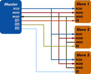
Using the “Slave Select” line, the master chooses which slave with which to communicate. Note that more than one slave may be selected, simply by applying a logic low to the desired SS lines, as illustrated in the schematic diagram shown above. If a given slave is not selected (its SS is high) it disregards signals sent by the master.
References
SPI Background.www.totalphase.com
Serial Peripheral Interface. Www.wikipedia.org
Circuit
Above shows the Master connected to three slaves. Each slave must be enabled through the slave select pin in order to communicate with the Master.
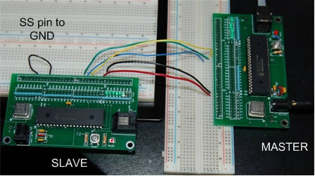
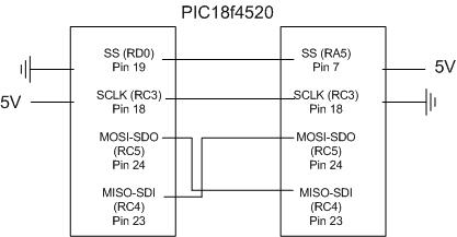
The two PICs can be wired directly by connecting these input and output pins of the diagram above.
Code (Code mentioned on this page does NOT work when tried with the PIC18F4520)
Hardware SPI Hardware SPI uses builtin hardware in the PIC18f4520 to send and receive SPI signals. First both master and slave must call the spi_setup() function. Then the master can send data with spi_write() and the slave can read with spi_read(). When using hardware SPI the slave will only listen to incoming data if the slave-select pin RA5 is pulled low.
/*MASTER CODE*/
/* This code is valid only for devices that support hardware spi such as the PIC18F4520. For all other devices use
software spi. This code does not work on PIC18F4520 and will require more experimentation. This is the code that
looks most promising to start with from our review of codes on the internet for hardware SPI*/

#include <18f4520.h>
#fuses HS,NOLVP,NOWDT,NOPROTECT
#use delay(clock=20000000)

void main(){

int value; 	//for 8 bit transfer which is default
int value_read; // to be read from spi

//it seems that the PIC does not generate proper output pulses in H_TO_L mode
//we had better success in L_TO_H mode
setup_spi(SPI_MASTER|SPI_H_TO_L|SPI_CLK_DIV_16); // sets the PIC as a master which generates the clock signal, a slower clock can be  generated by changing 16 to 64

 while (TRUE) {

      value = 4;     // value to be sent to spi

    //output_low(PIN_D0); //Turns on slave if slave select is used

      spi_write(value);

      value_read = spi_read();

      delay_us(100);

   // output_high(PIN_D0); //Turns off slave if slave select is used

   }

}

/*SLAVE CODE*/

/* This code is valid only for devices that support hardware spi such as the PIC18F4520. For all other devices use
software spi. This code does not work on PIC18F4520 and will require more experimentation. This is the code that
looks most promising to start with from our review of codes on the internet for hardware SPI*/

/* For hardware spi, library functions such as spi_setup(), spi_read() and spi_write() can be used */
/* For software spi, spi_xfer() can be used alongwith the #use spi directive*/
/* We are not entirely sure if an output pin of the master should be connected to the SS pin (A5 for PIC18f4520)
of the slave */
/* In most cases, simply grounding the SS pin of the slave should work */
/* slave code is really hard to find on the internet */


#include <18f4520.h>
#fuses HS,XT,NOLVP,NOWDT,NOPROTECT
#use delay(clock=20000000)

void main(){


int value_read; // to be read from spi

setup_spi(SPI_SLAVE|SPI_H_TO_L); // sets the PIC as a slave which recieves a clock signal and data is transferred during H to L

 while (TRUE) {


      value_read = spi_read(); // according to the reference manual this should work but also see the code below

     // if(spi_data_is_in())   // Checks to see if data is ready to be read
	//	value_read = spi_read(); //reads the data from spi

      delay_us(100);

      output_d(value_read);  //display the number that has been read
      spi_write(0);        // This is probably unnecessary

   }

}


/* WATCH OUT FOR UPDATES */
Software SPI
Below is some software SPI example code. Software SPI is enabled by the "#use spi" directive and, while slower than hardware SPI, can use any port as input or output. See the CCS compiler manual for more information on the "#use spi" directive options.
This code does not work either, though we can see on the oscilloscope that correct clock pulses and data pulses are being sent by the master. The slave receives a garbled message, however: it seems to be missing clock pulses and thus missing data bits.
//MASTER CODE

#include <18f4520.h>
#fuses HS,NOLVP,NOWDT,NOPROTECT
#use delay(clock=40000000)
#use spi(DO = PIN_C4, CLK = PIN_C3, BITS = 8, MASTER, MSB_FIRST, IDLE = 1)  //setup software SPI

void main() {
    while(true) {
        delay_ms(10);


        //send the byte "11001010"
        spi_xfer(0b11001010); //software SPI uses the spi_xfer function to both send and receive data
    }
}


//SLAVE CODE

#include <18f4520.h>
#fuses HS,NOLVP,NOWDT,NOPROTECT
#use delay(clock=40000000)
#use spi(DI = PIN_A3, CLK = PIN_A2BITS = 8, SLAVE, MSB_FIRST, IDLE = 1)

void main() {
    int data;

    while(true) {
        data = spi_xfer(0); //software SPI uses the spi_xfer function to both send and receive data
        output_d(data); //display the data we received
    }
}
Most of the sample code was obtained from the following sources
The CCS user manual


