Difference between revisions of "Optics"
| (4 intermediate revisions by one other user not shown) | |||
| Line 80: | Line 80: | ||
When the path of the light beam is not parallel to the axis of the lens, the beam still converges, however the convergence point is also off-axis. This results in a focal plane which is at the focal length. This plane is where parallel beams of light converge. Real images are all located beyond the focal plane, provided that the object emitting or reflecting the light is more than the focal distance in front of the lens. It is important to note that the location of the image plane is a function of the focal length of the lens and the distance from the lens to the object being imaged. |
When the path of the light beam is not parallel to the axis of the lens, the beam still converges, however the convergence point is also off-axis. This results in a focal plane which is at the focal length. This plane is where parallel beams of light converge. Real images are all located beyond the focal plane, provided that the object emitting or reflecting the light is more than the focal distance in front of the lens. It is important to note that the location of the image plane is a function of the focal length of the lens and the distance from the lens to the object being imaged. |
||
<br clear=all> |
|||
| ⚫ | |||
Assuming a negligible lens thickness, the relationship between the object distance, image distance, and focal length is given by the '''thin lens equation''': |
Assuming a negligible lens thickness, the relationship between the object distance, image distance, and focal length is given by the '''thin lens equation''': |
||
| Line 85: | Line 87: | ||
<math>\frac{1}{S_1} + \frac{1}{S_2} = \frac{1}{f}</math> |
<math>\frac{1}{S_1} + \frac{1}{S_2} = \frac{1}{f}</math> |
||
| ⚫ | |||
| Line 95: | Line 96: | ||
==Field of View== |
==Field of View== |
||
[[Image:field_of_view.gif|right|Determining the field of view of an optical sensor with a converging lens]|thumb|350px]] |
|||
The field of view (FoV) of a lens is a function of the focal length and the diameter of the imaging surface. Imagine that the lens is a small aperture in one end of an opaque cylinder of large diameter with the other end of the cylinder at the image plane. Assuming that the object being imaged is approximately at a distance of infinity, this would make the focal plane and the image plane the same. The radius of the cylinder is r, the focal length is f, and the field of view is 2*<math>\theta</math>. |
The field of view (FoV) of a lens is a function of the focal length and the diameter of the imaging surface. Imagine that the lens is a small aperture in one end of an opaque cylinder of large diameter with the other end of the cylinder at the image plane. Assuming that the object being imaged is approximately at a distance of infinity, this would make the focal plane and the image plane the same. The radius of the cylinder is r, the focal length is f, and the field of view is 2*<math>\theta</math>. |
||
<math> \theta=arctan \frac{r}{f}</math> |
<math> \theta=arctan \frac{r}{f}</math> |
||
In the above computation, r is actually the radius of the sensing area, so if the cylinder is actually larger than the sensing area, |
|||
only the range of angles where the light converges on the sensor will be included. This is because light reflected from a point in space toward the lens will have a narrow range of angles, which will converge on a single point in the image plane, resulting in clear images at that distance. The angular distance from the origin of the light to the axis of the lens will determine where in the image plane the light converges, so imagining that for a sensor at the image plane, light simply passes through an infinitesimally small hole at the lens position and emerges (inverted) to be projected on the sensor is an appropriate approximation. |
|||
<br clear=all> |
|||
Latest revision as of 13:51, 18 August 2009
Overview
This page describes the use of lenses and filters to manage the properties of light within a system. Common applications could include machine vision, color sensing, or laser direction.
Introduction
Lenses and filters manage the properties of light which passes through them. By selectively allowing light to pass through, filters can control color, light polarity and brightness. In this respect, a liquid-cristal display is simply a programmable filter.
Lenses are used to bend light into a new path. They use material density changes and curveatures to bend incoming or outgoing light into the desired path, either converging or diverging the beam.
Filters
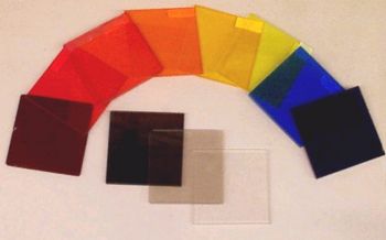
Filters generally absorb or reflect light of certain wavelengths (or within a certain range of wavelengths), while allowing all other light to pass. This is often achieved by doping the glass or polymer lens with organic and inorganic compounds which absorb light or by applying coatings to a glass or polymer substrate which reflect light of certain wavelength ranges. These distinctions are termed reflective or absorptive filtering, with the reflective filtering appearing mirror-like. So a one-way mirror is really a neutral density filter which is reflective, rather than absorptive.
Some filters are built to attenuate specific wavelengths (notch filters) or to pass only certain wavelengths (bandpass filters). Such filters can also be applied to wavelength ranges outside of the visible range, into the infrared (IR) or ultraviolet (UV) ranges. The dark plastic cases of some photodiodes or phototransistors are actually transparent in the infrared range, allowing them to send or receive infrared light without being affected by ambient visible light sources. There are also neutral-density filters which attenuate or reflect all wavelengths by approximately the same amount, resulting in a gray or mirrored appearance. These are often used to control overall intensity of the light reaching a sensor while maintaining the spectral composition of the light.
Refraction
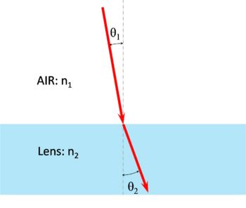
When light passes from one medium to another, its path is bent at the boundary. This bending is called refraction. Depending on the relative densities of the materials involved, the bending could be minor or severe. To quantify the relative optical density of an object, each material has an index of refraction, which is the ratio beteween the angle of entry and the angle of exit at the interface between a material and a vacuum. For transfers at boundaries between materials other than a vacuum, knowing the index of refraction (n) for each material at each boundary allows us to apply Snell's Law to find the respective refraction angle.
These refraction angles are different for different wavelengths of light, an effect called dispersion. In dispersive materials, the index of refraction would be a function of the frequency of the light which is passing through the material. This should only be significant if the application requires vision over a broad range of wavelengths with high precision.
Lens Shapes

The curveature of lens surfaces affects the convergence properties of the light passing through the lens. There are three general types of curveature:
- Convex - This is an outward curve and tends to converge light
- Concave - This is an inward curve and tends to diverge light
- Planar - This is a flat surface and serves to refract light uniformly, not adding properties to the lens.
The common types of lens shapes produced are:
- biconvex
- plano-convex
- positive meniscus
- negative meniscus
- plano-concave
- biconcave
Biconvex
A biconvex lens curves outward on both sides. When parallel beams of light pass through this lens, they converge on a single point regardless of where they enter the lens. Such lenses are commonly used in magnifying glasses, telescopes, microscopes, and binoculars. When used to make images, these lenses produce real inverted images, i.e. if the image were projected onto a flat surface the image would be inverted with respect to both axes.
Plano-Convex
A plano-convex lens has one flat side and one side which curves outward. When parallel beams of light pass through this lens, they converge on a single point regardless of where they enter the lens. Such lenses are commonly used in magnifying glasses, telescopes, microscopes, and binoculars. When used to make images, these lenses produce real inverted images, i.e. if the image were projected onto a flat surface the image would be inverted with respect to both axes.
Positive Meniscus
A positive meniscus lens has one side which curves outward and one side which curves inward, producing the "meniscus". The positive meniscus has a steeper convex surface (with respect to the radii of curveatures for the two sides). This results in the convergence of parallel beams of light which pass through this lens.
Negative Meniscus
A negative meniscus lens has one side which curves outward and one side which curves inward, producing the "meniscus". The negative meniscus has a steeper concave surface (with respect to the radii of curvatures for the two sides). This results in the divergence of parallel beams of light which pass through this lens.
Plano-Concave
A plano-concave lens has one flat side and one side which curves inward. When parallel beams of light pass through this lens, they diverge regardless of where they enter the lens. Such lenses are commonly used in human vision aids such as glasses or contact lenses. When used to make images, these lenses produce virtual non-inverted images, i.e. if the image were viewed through the lens, it would appear non-inverted and smaller than the actual object, but closer to the viewer, hence the vision correction.
Biconcave
A biconcave lens has two sides which curve inward. When parallel beams of light pass through this lens, they diverge regardless of where they enter the lens. Such lenses are commonly used in human vision aids such as glasses or contact lenses. When used to make images, these lenses produce virtual non-inverted images, i.e. if the image were viewed through the lens, it would appear non-inverted and smaller than the actual object, but closer to the viewer, hence the vision correction.
Focal Length
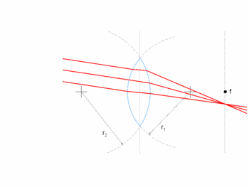
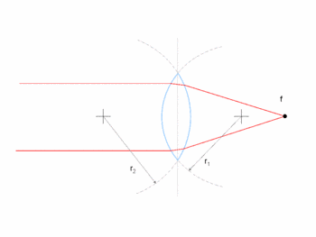
Most applications will employ converging (or positive) lenses, which is what will be described here. A converging lens causes a convergence of collimated (parallel) light, for example light emitted from a source an infinite distance from the lens. Such a beam of light will be refracted as it enters and again as it leaves the lens, resulting in paths which converge on a single point. Assuming that the path of the light beam is parallel to the axis of the lens, the point at which the beam converges is known as the focal point, and the distance from that point to the center of the lens is known as the focal length. The focal length is a function of the radii of curvature of the two faces of the lens, which is known as the [lens maker's equation, and holds for lenses in air. Under the conditions that the lens thickness is negligible with respect to the focal length, is the radius of curvature of the entry side of the lens, is the radius of curvature of the exit side of the lens, and positive radius of curvature represents convex curvature, the thin lens form of the lens maker's equation results in:
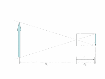
When the path of the light beam is not parallel to the axis of the lens, the beam still converges, however the convergence point is also off-axis. This results in a focal plane which is at the focal length. This plane is where parallel beams of light converge. Real images are all located beyond the focal plane, provided that the object emitting or reflecting the light is more than the focal distance in front of the lens. It is important to note that the location of the image plane is a function of the focal length of the lens and the distance from the lens to the object being imaged.
Assuming a negligible lens thickness, the relationship between the object distance, image distance, and focal length is given by the thin lens equation:
Additionally, there is a resolution to any optical sensors, which permits a certain amount of blurring in the image, permitting objects at distances similar to that of the imaged object to be "acceptably sharp" as well. The hyperfocal distance is the distance at which a lens is to be focused to make all objects from half the hyperfocal distance to infinity acceptably sharp. This is heavily dependent on the definition of "acceptably sharp" which is the size which an infinitesimally small point spreads out to on the imaging plane. So for crude applications, the hyperfocal distance will be relatively near, while for high precision optics the hyperfocal distance will be relatively far.
For more information, see http://en.wikipedia.org/wiki/Lens_(optics) where you can find information about some of the common sources of distortions in lenses and the properties of diverging lenses.
Field of View
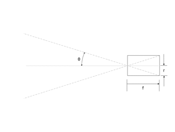
The field of view (FoV) of a lens is a function of the focal length and the diameter of the imaging surface. Imagine that the lens is a small aperture in one end of an opaque cylinder of large diameter with the other end of the cylinder at the image plane. Assuming that the object being imaged is approximately at a distance of infinity, this would make the focal plane and the image plane the same. The radius of the cylinder is r, the focal length is f, and the field of view is 2*.
In the above computation, r is actually the radius of the sensing area, so if the cylinder is actually larger than the sensing area,
only the range of angles where the light converges on the sensor will be included. This is because light reflected from a point in space toward the lens will have a narrow range of angles, which will converge on a single point in the image plane, resulting in clear images at that distance. The angular distance from the origin of the light to the axis of the lens will determine where in the image plane the light converges, so imagining that for a sensor at the image plane, light simply passes through an infinitesimally small hole at the lens position and emerges (inverted) to be projected on the sensor is an appropriate approximation.



![{\displaystyle {\frac {1}{f}}=(n-1)\left[{\frac {1}{r_{1}}}-{\frac {1}{r_{2}}}\right]}](https://wikimedia.org/api/rest_v1/media/math/render/svg/e8a35a6e82b22201c80ee15b5dd37d2f341d1e2b)
