Difference between revisions of "Ball Balancing Challenge"
| (14 intermediate revisions by 2 users not shown) | |||
| Line 1: | Line 1: | ||
[[image:T14-project-action-08.jpg| |
[[image:T14-project-action-08.jpg|350px|right]] |
||
| Line 20: | Line 20: | ||
[[Image:Motorandconnection.JPG|right|thumb|Faulhaber Motor with epoxy connection to metal frame|200px]] |
[[Image:Motorandconnection.JPG|right|thumb|Faulhaber Motor with epoxy connection to metal frame|200px]] |
||
=== Overview === |
|||
Our team weighed several alternatives for a mechanical system that could turn the screen in two axes. Potential solutions included a gimble system with a double-frame design and a pully-operated system that would lift up on two sides of the screen. Eventually, we decided on a system that was theoretically less precise, but much simpler and requiring less power (since one motor does not need to lift another). The system worked well under joystick control, but is only reliable for small tilting angles. |
Our team weighed several alternatives for a mechanical system that could turn the screen in two axes. Potential solutions included a gimble system with a double-frame design and a pully-operated system that would lift up on two sides of the screen. Eventually, we decided on a system that was theoretically less precise, but much simpler and requiring less power (since one motor does not need to lift another). The system worked well under joystick control, but is only reliable for small tilting angles. |
||
=== Mechanical Explanation === |
|||
A sheet metal frame was built around the frame for protection, supported at its center of gravity by a pillar attached to the wooden base. The frame can freely tilt in two directions, allowing all possible ball movements. By raising and lowering two adjacent sides of the frame, the touch screen can be tilted in two directions. This motion is provided by two [http://hades.mech.northwestern.edu/wiki/index.php/Actuators_Available_in_the_Mechatronics_Lab#Faulhaber_1524E006S_motor_with_141:1_gearhead_and_HES164A_magnetic_quadrature_encoder Faulhaber motors] mounted underneath the screen. The output shaft of the motors' gear boxes are attached to a threaded rod by couplers that we machined for the purpose. The couplers are attached to the motor shaft by a radial set screw and to the threaded rods by locking nuts. Riding on these rods are two threaded aluminum pieces, which are attached to the bottom of the frame via flexible tubing and epoxy. As the angle of the screen changes in one direction, the location of the attachment of the other motor moves slightly relative to the base of the motor. The flexible coupling allows for this motion, while providing vertical stability and transferring the up and down motion of the threaded pieces to the sides of the frame. [[Image:Coinslotopen.JPG|left|thumb|Coinslot with top off|200px]] Provided that the tilt angle remains small, its value can be approximated by the inverse tangent of the vertical motion of the threaded rod divided by 9cm (the horizontal distance from the tubing connection to the center of the frame). By controlling the speed of the motors via [http://hades.mech.northwestern.edu/wiki/index.php/Pulse_Width_Modulation pulse width modulation], the tilt angles of the touch screen can be changed at a variety of speeds. |
A sheet metal frame was built around the frame for protection, supported at its center of gravity by a pillar attached to the wooden base. The frame can freely tilt in two directions, allowing all possible ball movements. By raising and lowering two adjacent sides of the frame, the touch screen can be tilted in two directions. This motion is provided by two [http://hades.mech.northwestern.edu/wiki/index.php/Actuators_Available_in_the_Mechatronics_Lab#Faulhaber_1524E006S_motor_with_141:1_gearhead_and_HES164A_magnetic_quadrature_encoder Faulhaber motors] mounted underneath the screen. The output shaft of the motors' gear boxes are attached to a threaded rod by couplers that we machined for the purpose. The couplers are attached to the motor shaft by a radial set screw and to the threaded rods by locking nuts. Riding on these rods are two threaded aluminum pieces, which are attached to the bottom of the frame via flexible tubing and epoxy. As the angle of the screen changes in one direction, the location of the attachment of the other motor moves slightly relative to the base of the motor. The flexible coupling allows for this motion, while providing vertical stability and transferring the up and down motion of the threaded pieces to the sides of the frame. [[Image:Coinslotopen.JPG|left|thumb|Coinslot with top off|200px]] Provided that the tilt angle remains small, its value can be approximated by the inverse tangent of the vertical motion of the threaded rod divided by 9cm (the horizontal distance from the tubing connection to the center of the frame). By controlling the speed of the motors via [http://hades.mech.northwestern.edu/wiki/index.php/Pulse_Width_Modulation pulse width modulation], the tilt angles of the touch screen can be changed at a variety of speeds. |
||
=== Other features === |
|||
Other features include adjustable legs for stabilizing the wooden base on an uneven surface, and an upper frame above the touchscreen that prevents the ball from rolling onto the non-sensing regions at the periphery of the touchscreen. The mechanical design for this project was the simplest and most inexpensive option for this application; if a greater level of precision were required, a more complicated mechanism may have been necessary. |
Other features include adjustable legs for stabilizing the wooden base on an uneven surface, and an upper frame above the touchscreen that prevents the ball from rolling onto the non-sensing regions at the periphery of the touchscreen. The mechanical design for this project was the simplest and most inexpensive option for this application; if a greater level of precision were required, a more complicated mechanism may have been necessary. |
||
| Line 30: | Line 34: | ||
==Electrical Design== |
==Electrical Design== |
||
=== Overview === |
|||
The Electrical Design was fairly simple for this project. The inputs to the PIC were the joystick, coin slot, and the touchscreen. The outputs were the motors, LED "strike" array, and buzzer. The touchscreen was also an output as it was controlled by the PIC. |
The Electrical Design was fairly simple for this project. The inputs to the PIC were the joystick, coin slot, and the touchscreen. The outputs were the motors, LED "strike" array, and buzzer. The touchscreen was also an output as it was controlled by the PIC. |
||
[[Image:TouchscreenControlpanel.JPG|left|thumb|Touch screen controls and LED display|200px]] |
[[Image:TouchscreenControlpanel.JPG|left|thumb|Touch screen controls and LED display|200px]] |
||
=== PIC Inputs === |
|||
The user would control the joystick that was simply two potentiometers that would output a value between 0V and 5V, corresponding to both the x-axis and the y-axis. This went to one of the PIC's analog inputs. The coin would simply fall on a simple switch, connecting 5V to the PIC. The touchscreen input looks like a square wave, except the two values being received correspond to the voltage from each axis. Separating these two values is done in software. |
The user would control the joystick that was simply two potentiometers that would output a value between 0V and 5V, corresponding to both the x-axis and the y-axis. This went to one of the PIC's analog inputs. The coin would simply fall on a simple switch, connecting 5V to the PIC. The touchscreen input looks like a square wave, except the two values being received correspond to the voltage from each axis. Separating these two values is done in software. |
||
Toggle switches were added to allow easy powering on and off of our system. Also, a switch for automatic and manual control was implemented which was designed to have the purpose of switching the design from joystick control to automatic system control (self-adjusting touchscreen). The reset button was implemented to end the game at any time and end the main loop so that the motors would be inactive. |
Toggle switches were added to allow easy powering on and off of our system. Also, a switch for automatic and manual control was implemented which was designed to have the purpose of switching the design from joystick control to automatic system control (self-adjusting touchscreen). The reset button was implemented to end the game at any time and end the main loop so that the motors would be inactive. |
||
=== PIC Outputs === |
|||
The PIC output to the motors corresponds directly to the joystick input. The PIC output goes both to the H-bridge and an inverter for each motor, so that the motor sees not a PWM signal and ground, but a PWM signal with its inverse PWM signal. As a result of this, both poles of the motor see the same thing when the high and low pulses of the signal are equal. The motors turn one way proportionally to the joystick position when the PWM has more time high than low (when that joystick potentiometer is sending a higher signal)and the other way when the PWM is more low than high. |
The PIC output to the motors corresponds directly to the joystick input. The PIC output goes both to the H-bridge and an inverter for each motor, so that the motor sees not a PWM signal and ground, but a PWM signal with its inverse PWM signal. As a result of this, both poles of the motor see the same thing when the high and low pulses of the signal are equal. The motors turn one way proportionally to the joystick position when the PWM has more time high than low (when that joystick potentiometer is sending a higher signal)and the other way when the PWM is more low than high. |
||
The PIC output to the touchscreen is very simple. Although we had it go through an H-bridge to amplify the current, this is probably not necessary. Because the diagonally opposite corners of the touchscreen always have an opposite voltage going into them, we just ran the signal through an inverter so that we could control all four corners with only two PIC outputs. |
The PIC output to the touchscreen is very simple. Although we had it go through an H-bridge to amplify the current, this is probably not necessary. Because the diagonally opposite corners of the touchscreen always have an opposite voltage going into them, we just ran the signal through an inverter so that we could control all four corners with only two PIC outputs. |
||
| ⚫ | |||
=== Circuit Components === |
|||
| ⚫ | |||
| ⚫ | |||
| ⚫ | |||
| ⚫ | |||
<table border=1> |
<table border=1> |
||
<tr><th>Part</th><th>Part No.</th><th>Qty</th><th>Vendor</th><th>Price (Total)</th></tr> |
<tr><th>Part</th><th>Part No.</th><th>Qty</th><th>Vendor</th><th>Price (Total)</th></tr> |
||
| Line 57: | Line 64: | ||
</table> |
</table> |
||
| ⚫ | |||
| ⚫ | |||
| ⚫ | |||
[[Image:T14-schematic 1.JPG|center|thumb|Ball Balancing Circuit Diagram|600px]] |
[[Image:T14-schematic 1.JPG|center|thumb|Ball Balancing Circuit Diagram|600px]] |
||
| Line 64: | Line 73: | ||
This project was programmed using [[CCS C]] on a PIC 18F4520. See the page on [[4520 Board use]] for more information on using the boards we used. |
This project was programmed using [[CCS C]] on a PIC 18F4520. See the page on [[4520 Board use]] for more information on using the boards we used. |
||
=== Modular Code === |
|||
The opening lines are necessary for establishing that we are using a PIC 18F4520, analog inputs, a clock, connecting with an ICD, and that we are using pin 36 instead of 16 for the second PWM output. This is also where we establish all of our variables and functions. |
The opening lines are necessary for establishing that we are using a PIC 18F4520, analog inputs, a clock, connecting with an ICD, and that we are using pin 36 instead of 16 for the second PWM output. This is also where we establish all of our variables and functions. |
||
| Line 321: | Line 332: | ||
</pre> |
</pre> |
||
=== Full Code === |
|||
[[media:T14-source-code.c|See full code here]] |
[[media:T14-source-code.c|See full code here]] |
||
==Results |
==Results== |
||
Although we got our project to the point where it worked well enough to show that we were able to create a working game, we definitely fell short of our goal of implementing a control system of not only stabilizing the ball, but also controlling its position and responding to disturbances. Listed below are our successes that greatly contributed to this project, as well as how they could be improved upon. |
Although we got our project to the point where it worked well enough to show that we were able to create a working game, we definitely fell short of our goal of implementing a control system of not only stabilizing the ball, but also controlling its position and responding to disturbances. Listed below are our successes that greatly contributed to this project, as well as how they could be improved upon. |
||
| Line 392: | Line 404: | ||
The main problem with using this method was that we were having hard times reading the encoders, and it was very difficult to manually make the screen flat before every use, as would be necessary for this to work, as there was no other way to establish a base encounter count. |
The main problem with using this method was that we were having hard times reading the encoders, and it was very difficult to manually make the screen flat before every use, as would be necessary for this to work, as there was no other way to establish a base encounter count. |
||
Finally, the big problem we needed to tackle was a way to get a more consistent reading from the touchscreen, as this method led to a lot of false zeros. Putting a simple analog RC low pass filter did not work because the speed at which the PIC sampled the signal was too high, and the shaping of the curve would throw off the readings. A more complex analog filter might have improved this situation, but we chose to instead explore software filters. The software filters were moderately more successful, but they weren't perfect and they caused our code to severely lack resolution in the readings, as too many of the values were thrown out. The problem might be fixed mechanically if a game piece with a higher friction coefficient were used than the steel ball, such as a square slider. Alternatively, a different type of touchscreen could be used, such as an |
Finally, the big problem we needed to tackle was a way to get a more consistent reading from the touchscreen, as this method led to a lot of false zeros. Putting a simple analog RC low pass filter did not work because the speed at which the PIC sampled the signal was too high, and the shaping of the curve would throw off the readings. A more complex analog filter might have improved this situation, but we chose to instead explore software filters. The software filters were moderately more successful, but they weren't perfect and they caused our code to severely lack resolution in the readings, as too many of the values were thrown out. The problem might be fixed mechanically if a game piece with a higher friction coefficient were used than the steel ball, such as a square slider. Alternatively, a different [http://en.wikipedia.org/wiki/Touchscreen#Technologies type of touchscreen] could be used, such as an infrared touchscreen. |
||
Latest revision as of 02:23, 21 March 2008
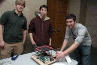
Team Members
- JJ Darling - Electrical Engineering Class of 2009
- Ben Schriesheim - Manufacturing Engineering Class of 2008
- Alex Leung - Biomedical Engineering MS 2009
Overview
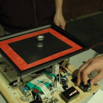
Based off an original idea of ball juggling, the purpose of our project was to test and gauge the capability of using a resistive touchscreen with a PIC Microcontroller. Our original projected means for testing the touchscreen for our project was to attempt to design and implement a system that would keep a round metal ball in the center of the touchscreen. Using the touchscreen's analog outputs of position, we would design a control system that would use a two-axis actuator system to move the touchscreen up and down depending on disturbances to keep the metal ball in the same place. Automatic control and manual control elements were to be implemented with the manual control element.
However, due to complications with our touchscreen readings, our group decided to focus on the essentials of our project and have it focus on both the touchscreen capabilities and try to make the project as interactive as possible. A joystick (made from two potentiometers) was used to control the two motors which would lift the table up in either axis. The game begins with a coin machine which, when a coin is slided in, would set off a contact and initiate the motor control. The design of our game was so that the player would attempt to keep the ball in a restricted region in the middle of the touchscreen, which was marked in black. The outside region of the touchscreen, marked in red, would set off LED's that would go off if the player stayed in the red region for an extended time. The player would lose after 4 LED's light up and the buzzer goes off. The player can reset the game but the motor control would cease to function and a coin is needed to reactivate the game again.
Mechanical Design
Overview
Our team weighed several alternatives for a mechanical system that could turn the screen in two axes. Potential solutions included a gimble system with a double-frame design and a pully-operated system that would lift up on two sides of the screen. Eventually, we decided on a system that was theoretically less precise, but much simpler and requiring less power (since one motor does not need to lift another). The system worked well under joystick control, but is only reliable for small tilting angles.
Mechanical Explanation
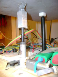
A sheet metal frame was built around the frame for protection, supported at its center of gravity by a pillar attached to the wooden base. The frame can freely tilt in two directions, allowing all possible ball movements. By raising and lowering two adjacent sides of the frame, the touch screen can be tilted in two directions. This motion is provided by two Faulhaber motors mounted underneath the screen. The output shaft of the motors' gear boxes are attached to a threaded rod by couplers that we machined for the purpose. The couplers are attached to the motor shaft by a radial set screw and to the threaded rods by locking nuts. Riding on these rods are two threaded aluminum pieces, which are attached to the bottom of the frame via flexible tubing and epoxy. As the angle of the screen changes in one direction, the location of the attachment of the other motor moves slightly relative to the base of the motor. The flexible coupling allows for this motion, while providing vertical stability and transferring the up and down motion of the threaded pieces to the sides of the frame.
Provided that the tilt angle remains small, its value can be approximated by the inverse tangent of the vertical motion of the threaded rod divided by 9cm (the horizontal distance from the tubing connection to the center of the frame). By controlling the speed of the motors via pulse width modulation, the tilt angles of the touch screen can be changed at a variety of speeds.
Other features
Other features include adjustable legs for stabilizing the wooden base on an uneven surface, and an upper frame above the touchscreen that prevents the ball from rolling onto the non-sensing regions at the periphery of the touchscreen. The mechanical design for this project was the simplest and most inexpensive option for this application; if a greater level of precision were required, a more complicated mechanism may have been necessary.
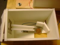
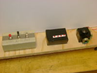
The coin slot box was simply a ramp that would lead the dropped coin onto a conducting plate. The plate was supported by a weak spring that would bend under the weight of the coin to briefly touch another conducting plate below it before the coin rolled off. The brief contact between the two plates would send a high voltage to the PIC microcontroller.
Electrical Design
Overview
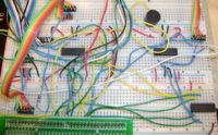
The Electrical Design was fairly simple for this project. The inputs to the PIC were the joystick, coin slot, and the touchscreen. The outputs were the motors, LED "strike" array, and buzzer. The touchscreen was also an output as it was controlled by the PIC.
PIC Inputs
The user would control the joystick that was simply two potentiometers that would output a value between 0V and 5V, corresponding to both the x-axis and the y-axis. This went to one of the PIC's analog inputs. The coin would simply fall on a simple switch, connecting 5V to the PIC. The touchscreen input looks like a square wave, except the two values being received correspond to the voltage from each axis. Separating these two values is done in software.
Toggle switches were added to allow easy powering on and off of our system. Also, a switch for automatic and manual control was implemented which was designed to have the purpose of switching the design from joystick control to automatic system control (self-adjusting touchscreen). The reset button was implemented to end the game at any time and end the main loop so that the motors would be inactive.
PIC Outputs
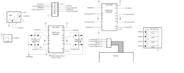
The PIC output to the motors corresponds directly to the joystick input. The PIC output goes both to the H-bridge and an inverter for each motor, so that the motor sees not a PWM signal and ground, but a PWM signal with its inverse PWM signal. As a result of this, both poles of the motor see the same thing when the high and low pulses of the signal are equal. The motors turn one way proportionally to the joystick position when the PWM has more time high than low (when that joystick potentiometer is sending a higher signal)and the other way when the PWM is more low than high.
The PIC output to the touchscreen is very simple. Although we had it go through an H-bridge to amplify the current, this is probably not necessary. Because the diagonally opposite corners of the touchscreen always have an opposite voltage going into them, we just ran the signal through an inverter so that we could control all four corners with only two PIC outputs.
Circuit Components
Information about the specifics, implementation and code that was used for the reading of the resistive touchscreen can be found here.
Parts List:
| Part | Part No. | Qty | Vendor | Price (Total) |
|---|---|---|---|---|
| Microchip 8-bit PIC Microcontroller (U1) | PIC18F4520 | 1 | N/A | N/A |
| Quadruple Half-H Drivers | L293D | 2 | Digi-Key | $1.93 |
| Hex Inverter | SN74HC04 | 1 | Digi-Key | $0.47 |
| Touchscreen | BER237-ND | 1 | Digi-Key | $62.00 |
| Joystick | N/A | 1 | N/A | N/A |
Diagram:
Software Design
This project was programmed using CCS C on a PIC 18F4520. See the page on 4520 Board use for more information on using the boards we used.
Modular Code
The opening lines are necessary for establishing that we are using a PIC 18F4520, analog inputs, a clock, connecting with an ICD, and that we are using pin 36 instead of 16 for the second PWM output. This is also where we establish all of our variables and functions.
#include <18f4520.h>
#DEVICE ADC=8                      // set ADC to 8 bit accuracy
#fuses HS,NOLVP,NOWDT,NOPROTECT, CCP2B3      // CCP2B3 moves PWM2 output to pin 36 (RB3) rather than pin 16 (RC1)
#device icd=true
#use delay(clock=20000000)


int yread,xread,m,j=0;
int read1pwm,read2pwm=0;
int read1,read2=0;
int coin,strike,ball=0;
signed int16 counter=0;

void buzz();
The main function starts with setting the correct initial values to the variables, and setting up the timers and analog ports.
void main() {
   //Flash 3 times to let us know we're running
   for (j=0;j<3;j++){
      output_d(0b11111111);
      delay_ms(250);
      output_d(0);
      delay_ms(250);
   }

   coin=0;
   strike=0;
   ball=0;
   counter=0;

   output_high(PIN_C1);          //Start with UL high, LR low ***THESE WILL CHANGE***
   output_high(PIN_C0);          //This is the pin for UR. It will be run through an inverter for LL
                                 //the bottom left corner. ***THESE ARE PERMANENT***

   setup_adc_ports(AN0_TO_AN2);        // Enable analog inputs; choices run from just AN0, up to AN0_TO_AN11
   setup_adc(ADC_CLOCK_INTERNAL);      // the range selected has to start with AN0

   setup_timer_2(T2_DIV_BY_4, 77, 16);        // clock at 16KHz, interrupt every 4*50nS * 4 * (155+1) * 16 = 2.00mS

   enable_interrupts(INT_TIMER2);
   enable_interrupts(GLOBAL);

   setup_ccp1(CCP_PWM);       // PWM output on CCP1/RC2, pin 17   this goes to y-axis motor
   setup_ccp2(CCP_PWM);       // PWM output on CCP2/RB3, pin 36   this goes to x-axis motor

   set_pwm1_duty(39);
   set_pwm2_duty(39);
The following portion of code shows what happens when the game is continuously played. First the game waits for a coin, then it plays the game until the user strikes out, then it stops the motors from spinning and again waits for a coin.
   while (TRUE) {

      set_pwm1_duty(39);
      set_pwm2_duty(39);

      //Wait for coin to be inserted
      while (coin==0) {
         if (input(PIN_E1)) coin=1;
         else delay_ms(100);
      }

      //Gameplay begins. Controls go dead when strikes go too high;
      while (coin==1) {
The touchscreen is read by having the PIC send alternating signals to 2 of the corners that are diagonal to each other while keeping the other two signals constant. This allows the touchscreen to read both axes each run through, and then display them in a manner where the x-axis reading corresponds to PIC LED outputs D0-D3, and the y-axis reading corresponds to outputs D4-D7. Although this gives visually a very poor resolution on the reading, it serves well enough as a debugging tool to make sure the reading is working.
         //Touchscreen reading, looks at the touchscreen readings
         if (m==0) {
            output_high(PIN_C1);       //UL goes high, thus LR goes low; y-axis can be read
            set_adc_channel(0);
            delay_us(10);
            yread = read_adc();       //Read y axis
            m++;
         }
         else {
            output_low(PIN_C1);        //UL goes low, thus LR goes high; x-axis can be read
            set_adc_channel(0);
            delay_us(10);
            xread = read_adc();       //Read x axis
            m=0;
         }


         //LED readings for XY locations of the touchscreen
         if (xread<75) {
            output_low(PIN_D0);
            output_low(PIN_D1);
            output_low(PIN_D2);
            output_low(PIN_D3);
         }
         else if (xread<110) {
            output_high(PIN_D0);
            output_low(PIN_D1);
            output_low(PIN_D2);
            output_low(PIN_D3);
         }
         else if (xread<145) {
            output_high(PIN_D0);
            output_high(PIN_D1);
            output_low(PIN_D2);
            output_low(PIN_D3);
         }
         else if (xread<180) {
            output_high(PIN_D0);
            output_high(PIN_D1);
            output_high(PIN_D2);
            output_low(PIN_D3);
         }
         else  {
            output_high(PIN_D0);
            output_high(PIN_D1);
            output_high(PIN_D2);
            output_high(PIN_D3);
         }
         if (yread<75) {
            output_low(PIN_D4);
            output_low(PIN_D5);
            output_low(PIN_D6);
            output_low(PIN_D7);
         }
         else if (yread<110) {
            output_high(PIN_D4);
            output_low(PIN_D5);
            output_low(PIN_D6);
            output_low(PIN_D7);
         }
         else if (yread<145) {
            output_high(PIN_D4);
            output_high(PIN_D5);
            output_low(PIN_D6);
            output_low(PIN_D7);
         }
         else if (yread<180) {
            output_high(PIN_D4);
            output_high(PIN_D5);
            output_high(PIN_D6);
            output_low(PIN_D7);
         }
         else  {
            output_high(PIN_D4);
            output_high(PIN_D5);
            output_high(PIN_D6);
            output_high(PIN_D7);
         }
To find the "winning" ranges of the black area on the touchscreen, we measured the voltage output on each axis on each boundary line, and converted it from the 0V to 5V scale to the quantized 8 bit (0 to 255) scale. Our code then checks to see if the ball is not in this zone before assigning a strike to the user. The counter variable is to ensure that the ball is outside the range enough times in a row, and a low reading is not simply the result of inconsistencies in the touchscreen reading. To stop the machine from simply running up the strikes while the ball is in the red, the code ensures that a "strike" cannot be assigned until a "ball" is assigned before hand.
For each strike, a corresponding LED is lit up, and upon the last strike, the buzz function is set off.
         //Check to see if the Ball is outide the allowed range of values to be "in the black" of the touchscreen
         if ((yread< 90) | (yread >150) | (xread <90) | (xread > 150)) {
            counter++;
            if ((counter==3) && (strike==ball)) {
               strike++;         //If ball is "in the red" for a sufficiently long time, a strike is added.
            }
         }
         else {
            counter--;
            //Check to see if the ball has returned from being "in the red."
            if ((counter==-1)  && (strike>ball)) {
               ball++;
            }
         }

         if ((counter==3) | (counter == -2)) counter=0;


         if (strike==2) {
            output_high(PIN_A3);
         }
         if (strike==3) {
            output_high(PIN_A4);
         }
         if (strike==4) {
            output_high(PIN_A5);
         }
         if (strike==5) {
            output_high(PIN_E2);
            set_pwm1_duty(39);
            set_pwm2_duty(39);
            buzz();
         }
The PIC reads the joystick and quantizes the input from the analog 0V to 5V to the 8 bit quantized 0 to 255. It then scales that number to be between 0 and 78, the PWM extremes.
         //Joystick Control
         if (input(PIN_C7) != 0) {  // toggle switch that switches between Joystick control system and Touchscreen control system
            set_adc_channel(2);     // there's only one ADC so select which input to connect to it; here pin AN1
            delay_us(10);           // wait 10uS for ADC to settle to a newly selected input
            read1 = read_adc();                       //x-axis
            if (read1<145 && read1>115) read1pwm=39;
            else read1pwm=(read1*.3);
            set_pwm1_duty(read1pwm);

            set_adc_channel(1);     // there's only one ADC so select which input to connect to it; here pin AN2
            delay_us(10);           // wait 10uS for ADC to settle to a newly selected input
            read2 = read_adc();                      //y-axis
            if (read2<145 && read2>115) read2pwm=39;
            else read2pwm=(read2*.3);
            set_pwm2_duty(read2pwm);
         }
         else {
            output_d(0);
            set_pwm1_duty(39);
            set_pwm2_duty(39);
         }
      }
   }
}
The buzz() function resets the counting variables to zero and sets the buzzer off by oscillating a PIC output into a basic buzzer speaker at an audible frequency.
void buzz() {

   coin=0;
   strike=0;
   ball=0;
   counter = 0;
   output_low(PIN_A3);
   output_low(PIN_A4);
   output_low(PIN_A5);
   output_low(PIN_E2);


   while (input(PIN_C6)==0) {
      output_high(PIN_C4);
      delay_us(100);
      output_low(PIN_C4);
      delay_us(100);
   }
}
Full Code
Results
Although we got our project to the point where it worked well enough to show that we were able to create a working game, we definitely fell short of our goal of implementing a control system of not only stabilizing the ball, but also controlling its position and responding to disturbances. Listed below are our successes that greatly contributed to this project, as well as how they could be improved upon.
- A robust mechanical design that allowed for more than adequate range of screen tilting, as well as good choices of equipment and materials for not only the job at hand, but also future implementations.
- The one shortcoming in this department is we should have had a higher threading ratio in that the linear motion of the screen should be greater per motor revolution in order to have a faster response.
- We were able to have proportional control between the position of the joystick and the speed of the motors.
- For automatic control we should have the tilting of the joystick proportional to the angle of the screen instead of the speed. We got this working to an extent before we scrapped the automatic contol. It is further explained below.
- We had a successful electric design that allowed for great flexibility within the software to do what we needed, while using a minimal amount of PIC inputs.
- The source code we wrote ended up being clean, well commented, and easy to modify and experiment with. The modular approach that we took with it will be helpful to future groups who will easily be able to glean portions of the code.
- Unfortunately the code had a couple bugs in it that were only able to be ironed out after the equipment was returned, including a poorly placed delay that caused a terrible refresh rate in the touchscreen and joystick response. These bugs caused a lot of gameplay issues, but although we have not been able to test the improved code, the changes we made were definitely harmless and would have greatly improved the gameplay.
- The game ended up being fun to play, and allowed for true interaction between man and machine. We were also able to successfully use the touchscreen, adding valuable information to the wiki about a previously unused technology.
- The responses of the game were clunky, the results of the game were somewhat unpredictable, and our coin slot didn't work as seamlessly with the rest of the system as we would have liked.
Future Action
The main thing that would have been improved in our project if we had more time is the PIC control of the touchscreen. We put a great deal of effort into getting it working, but we simply ran out of time and had to scrap that idea not long before the project was due. Mechanically, we needed to have a better threading ratio on the bolts, and a more powerful motor would probably help as well. The rest of the work would be done on paper and in software.
On paper, the first thing we would need to figure out a PD control system to control this ball. This would consist of an equation that relates the tilting angle necessary to counteract proportionally both the position of the ball on the touchscreen as well as the velocity of the ball. Counteracting the position of the ball would be very easy, and could simply be worked in software by telling the motors to tilt the screen so that it would roll towards the center, or whatever point we tell it to go to. Counteracting the velocy would be more tricky, as we would have to calculate the momentum of the ball, and then figure out the force necessary for counteracting the momentum. The screen would then have to be tilted so that the sine of the tilting angle times the gravitational constant would equal the necessary stopping force. We drafted some code for finding the velocity of the ball:
   //Measure velocity readings for motor encoder
   if (xcount>40 && ycount>40) {
      xold=xnew;
      xnew = (xmeasure/xcount);
      yold=ynew;
      ynew = (ymeasure/ycount);
      xvelocity = (xnew-xold);
      yvelocity = (ynew-yold);
      xcount=0;
      ycount=0;
      xmeasure=0;
      ymeasure=0;
      }
This code averages good values (not misreadings) of each axis readings and then subtracts the from the old average to get a number that corresponds to a velocity. The main problem with this is that the occurence of misreadings was generally very high because of the small contact point between the steel ball and the screen.
We also drafted some code to read the encoders and tilt the screen to the correct angle:
//Moves the motor to a pre-defined angle
void GoToAngle(int xangle,int yangle) {
   while ((Encoder1 < (angleref[xangle]-100)) && (Encoder1 > (angleref[xangle]+100)) ) {
      if (Encoder1<angleref[xangle]) set_pwm1_duty(78);
      if (Encoder1>angleref[xangle]) set_pwm1_duty(0);
   }
   while ((Encoder2 > (angleref[yangle]-100)) && (Encoder2 > (angleref[yangle]+100)) ) {
      if (Encoder2<angleref[yangle]) set_pwm2_duty(78);
      if (Encoder2>angleref[yangle]) set_pwm2_duty(0);
   }
   set_pwm1_duty(39);
   set_pwm2_duty(39);
}
int angleref[51] = {0, 91, 182, 273, 364, 455, 546, 637, 728, 819, 910, 1000, 1091, 1182, 1273, 1364, 1455, 1546, 1637, 1728, 1819, 1910,
                     2001, 2091, 2182, 2273, 2364, 2455, 2546, 2637, 2727, 2818, 2909, 3000, 3091, 3181, 3272, 3363, 3454, 3545, 3635, 3726,
                      3817, 3907, 3998, 4089, 4179, 4270, 4361, 4451, 4542};
The first box is the function that takes a desired x-angle and a desired y-angle and tells the motor to move to that position as fast as possible. The angles passed to the function are actually a value 10 times the angle (e.g. to move the screen to 2.5 degrees on the x-axis and 3.7 on the y-axis one would type
GoToAngle(25,37)
). The second box is an array containing the encoder values associated with the the angle of one tenth of their index. For example, to encrease a tilt by 1.0 degrees, the encoder count would have to increase by the value of angleref[10], which is 910.
The main problem with using this method was that we were having hard times reading the encoders, and it was very difficult to manually make the screen flat before every use, as would be necessary for this to work, as there was no other way to establish a base encounter count.
Finally, the big problem we needed to tackle was a way to get a more consistent reading from the touchscreen, as this method led to a lot of false zeros. Putting a simple analog RC low pass filter did not work because the speed at which the PIC sampled the signal was too high, and the shaping of the curve would throw off the readings. A more complex analog filter might have improved this situation, but we chose to instead explore software filters. The software filters were moderately more successful, but they weren't perfect and they caused our code to severely lack resolution in the readings, as too many of the values were thrown out. The problem might be fixed mechanically if a game piece with a higher friction coefficient were used than the steel ball, such as a square slider. Alternatively, a different type of touchscreen could be used, such as an infrared touchscreen.
