Difference between revisions of "IR communication between PICs"
Victor Liu (talk | contribs) |
|||
| (124 intermediate revisions by 5 users not shown) | |||
| Line 1: | Line 1: | ||
== Original Assignment == |
|||
Two PICs wired together can talk to each other using RS-232. Instead of wiring them together, we can use infrared transceivers so they communicate by IR. The goal of this project is to demonstrate bidirectional communication between two PICs using 38 kHz IR communication. Optional: show that these PICs can also receive data from a standard TV remote. |
|||
The Original Assignment indicates what you were assigned to do, and will eventually be erased from the final page. |
|||
== Overview == |
== Overview == |
||
The Overview is your rewritten version that clearly indicates what the page is about (to future students accessing the page) and |
|||
should also include links to other good web sources of information on this topic |
|||
Two PICs can easily communicate with one another using serial communication. IR communication is a basic extension of this method which can be easily implemented with a microcontroller (PIC) through an IR Encoder/Decoder (endec) and an IR Transceiver. The endec and transceiver used in this example support Serial IR (SIR) data rate, ranging from 9.6 kbps to 115.2 kbps. The typical range of the transceiver is nominally from 2 inches to 2 feet and extends upwards of 12 feet. The PIC, endec, and transceiver employed all support bidirectional use. However, when a transceiver is transmitting it essentially blinds its receiver and therefore cannot attain true full-duplex communication; only half-duplex was used with the transceiver taking turns transmitting and receiving. |
|||
== Circuit == |
|||
The Circuit shows a professional-looking circuit diagram including part numbers and where they can be obtained (and, where helpful, a photo of a neatly wired implementation of the circuit) |
|||
[[Image: |
[[Image:ir_transceiver.jpg|thumb|right|300px|IR Transceiver]] |
||
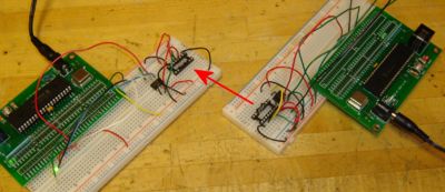
When transmitting, the PIC sends the serial format data to the endec, which encodes (or modulates) it bit by bit. This encoded data is then outputted as electrical pulses to the transceiver. The transceiver converts these electrical pulses to IR light pulses. When receiving, the transceiver receives IR light pulses (data), which are outputted as electrical pulses. The endec decodes (or demodulates) these electrical pulses, with the data then being transmitted by the endec UART back to the receiving PIC. This modulation/demodulation method is performed in accordance with the IrDA standard. |
|||
In my younger and more vulnerable years my father gave me some advice that I've been turning over in my mind ever since. "Whenever you feel like criticizing any one," he told me, "just remember that all the people in this world haven't had the advantages that you've had." He didn't say any more but we've always been unusually communicative in a reserved way, and I understood that he meant a great deal more than that. In consequence I'm inclined to reserve all judgments, a habit that has opened up many curious natures to me and also made me the victim of not a few veteran bores. |
|||
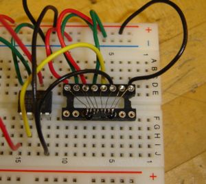
Both the PIC and the endec used in this example were DIP packages, making them easy to prototype and inspect. The transceiver, however, was a surface mount chip with an uncommon pin configuration (0.95 mm pitch), requiring a different mounting approach. The simplest solution was to glue the transceiver onto one side of a 16 pin socket, and then soldering small wires from the 8 pins of the transceiver onto the pins of the socket (see image). In the previous years, other mounting methods were tried, including the use of a [http://www.radioshack.com/sm-2-sided-copper-clad-pc-board--pi-2102495.html copper-clad board] or a [http://www.schmartboard.com/index.asp?page=products_so&id=54 SchmartBoard]. However, these approaches saw limited success. |
|||
<!--We initially attempted to etch a [http://www.radioshack.com/sm-2-sided-copper-clad-pc-board--pi-2102495.html copper-clad board] for our circuit (see image). However, due to the way this board is set up, this attempt only works with exact precision. Unfortunately, due to the limited number of IR transceivers and copper-clad boards we had this approach led to a dead end. Another possible solution to mount the IR transceiver was to use a [http://www.schmartboard.com/index.asp?page=products_so&id=54 SchmartBoard]. These boards are more general and pre-fabricated for use with surface mount ICs (with a particular pitch or pin seperation). Theoretically, both solutions will allow for connections to a solderless breadboard. However, because none of the IR transceiver chips we could find came at the same pitch as the SchmartBoards, we could not use this approach. Overall, since the IR transceiver chips did not come at standard pitches, we were unable to find a way to mount the IR chip.--> |
|||
Once upon a midnight dreary, while I pondered, weak and weary, |
|||
== Circuit == |
|||
Over many a quaint and curious volume of forgotten lore — |
|||
[[Image:IR_circuit.jpg|thumb|right|400px|Circuit Diagram]] |
|||
[[Image:ir_source.jpg|thumb|right|400px|Actual Circuit (Receiver)]] |
|||
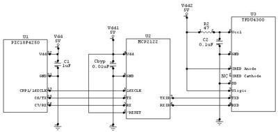
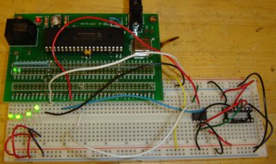
The circuit diagram shows a complete half-duplex IR communication circuit. This circuit can either be used together with an identical circuit to communicate, with only one PIC transmitting at a time, or with a remote control. The software on the PIC can be configured to respond to a variety of commands sent by the remote. The electrical characteristics of the power supply and discrete components are given below. Some of the ranges for the IR circuitry are also given below in parentheses. In the circuit, there are two interfaces: the serial interface and the IR interface. |
|||
While I nodded, nearly napping, suddenly there came a tapping, |
|||
===Serial Interface=== |
|||
As of some one gently rapping, rapping at my chamber door. |
|||
The serial interface is located between the PIC and the endec and sends data sequentially one bit at a time. The transmit (TX) and receive (RX) pins on the endec need to be connected between both ICs with a common ground. The data passing between the two components on these lines have the standard 8-N-1 serial data format. 8-N-1 is a serial configuration in which there are 8 data bits, no parity bits and 1 stop bit. Data bits contain the information to be transmitted. A parity bit is a binary digit used to ensure data accuracy, while a stop bit is used to indicate the end of a data string. |
|||
There is also a 16XCLK signal going to the endec from the PIC used to control the baud rate of the endec; that signal is a square wave pulse train at a frequency of 16*(the baud rate) and is generated in software. The <span style="text-decoration: overline">RESET</span> signal on the endec could be controlled with software but is simply held high since the endec need not be reset. |
|||
"'Tis some visiter," I muttered, "tapping at my chamber door — |
|||
<!--[[Image:Serial_ir_data_format.jpg|right|thumb|400px|Serial & IR Data Format]]--> |
|||
Only this and nothing more." |
|||
[[Image:ir_connect.jpg|right|thumb|400px|Source PIC Transmitting to the Receiver PIC]] |
|||
== |
===IR Interface=== |
||
The second interface — the IR interface — is located between the endec and the transceiver. This interface is straightforward with the TXIR and RXIR pins of the endec connecting to the TXD and RXD pins of the transceiver, respectively, and also has a common ground. The signals between these two components conform to the IrDA physical layer standard. When a logic high or '1' is to be transmitted, a logic low will be sent to the transceiver. When a logic low or '0' is to be transmitted, a logic high will be pulsed after 7-8 cycles of the 16XCLK signal for 3 cycles of the 16XCLK signal but no longer than 4 µs. |
|||
===Optical Interface=== |
|||
Code gives a listing of the liberally commented code, which should otherwise be as simple as possible (do not have extraneous lines of |
|||
The optical interface refers to the actual IR energy being transmitted between two transceivers or a source and a receiver. The optical signal is a modulated form of the signal between the Endec and the Transceiver at the Transceiver's carrier frequency, 38 kHz. That means that when the Endec would transmit a pulse for 3 cycles at the 16XCLK frequency, the transceiver would start pulsing IR energy at 38 kHz until the pulse went low. When the transceiver receive IR pulsed at 38 kHz, the duration of the IR pulses is the duration of the pulse sent to the Endec. |
|||
code that don't relate directly to the objective of the page). |
|||
===Electrical Characteristics=== |
|||
a character space starts code formatting |
|||
''Microcontroller ([http://ww1.microchip.com/downloads/en/DeviceDoc/39631a.pdf Microchip PIC18F4520])'' |
|||
*V<sub>DD</sub> = 5.0V |
|||
*C<sub>1</sub> = 1µF |
|||
**V<sub>DD</sub> - Pin 11 & 32 |
|||
**GND - Pin 12 & 31 |
|||
**TX - Pin 25 (C6) |
|||
**RX - Pin 26 (C7) |
|||
**16XCLK - Pin 17 (C2/CCP1) |
|||
''IR Encoder/Decoder ([http://ww1.microchip.com/downloads/en/DeviceDoc/21894c.pdf Microchip MCP2122-E/P])'' |
|||
two character spaces starts code formatting as well |
|||
*V<sub>DD</sub> = 5.0V (1.8V-5.5V) |
|||
*C<sub>BYP</sub> = 0.01µF |
|||
''IR Transceiver ([http://www.vishay.com/docs/82614/tfdu4300.pdf Vishay TFDU4300])'' |
|||
THREE character spaces |
|||
*V<sub>cc1</sub> = 5.0V (2.4V-5.5V) |
|||
*V<sub>cc2</sub> = 5.0V (-0.3V-6.0V) |
|||
*V<sub>logic</sub> = 5.0V (1.5V-5.5V) |
|||
*R<sub>2</sub> = 47Ω |
|||
*C<sub>2</sub> = 0.1µF |
|||
=== Limitations === |
|||
FIFTEEN CHARACTER SPACES |
|||
*IR Communication is only Half-Duplex (only one transceiver transmitting at a time) |
|||
*Transmission Distance maximum is about 12 feet (about 3ft in low power mode) |
|||
*Transmission is easily blocked or reflected by obstacles |
|||
*Communication Speed can only go up to 115.2 kpbs |
|||
== Code == |
|||
= External Links and Further Reading = |
|||
*[http://depot.northwestern.edu/djp133/ME_333/tfdu4300.pdf IR Transceiver Data Sheet] |
|||
Example code for a simple IR communication receiver circuit: |
|||
*[http://depot.northwestern.edu/djp133/ME_333/21894c.pdf IR Encoder/Decoder Data Sheet] |
|||
/* |
|||
*[http://www.schmartboard.com/ Prototyping boards for SMT] |
|||
ircomm.c Jennifer Breger, Brian Lesperance, Dan Pinkawa 2008-02-05 |
|||
Using the PIC's built-in UART, a counter continually is sent to one IR encoder/decoder. Then |
|||
the first IR encoder/decoder feeds its TXIR to the RXIR of a second IR encoder/decoder. The |
|||
second IR encoder/decoder then transmits back to the PIC what it is receiving. When the |
|||
transceiver circuit is properly mounted and inserted into the circuit, this code can be adapted |
|||
for half-duplex communication w/ another IR communications circuit. |
|||
*/ |
|||
/* |
|||
Edits by Jad Carson, Victor Liu, Matt Watras 2009-02-04 |
|||
*/ |
|||
#include <18f4520.h> |
|||
#fuses HS,NOLVP,NOWDT,NOPROTECT |
|||
#use delay (clock=40000000) |
|||
#use rs232(baud=9600, xmit=PIN_C6, rcv=PIN_C7, stream=com_a) // Initializes the UART to 9600 bps |
|||
// (up to 115,200 bps) |
|||
// timed_getc() checks whether data is ready to be read. If it's not the function returns a null |
|||
// character. If you simply use getc(), the PIC might get slowed up if the data isn't ready right |
|||
// away. |
|||
int timed_getc(void){ |
|||
long timeout; |
|||
int timeout_error = FALSE; |
|||
timeout = 0; |
|||
while(!kbhit() && (++timeout<50000)) |
|||
delay_us(10); |
|||
if (kbhit()) |
|||
return(getc()); |
|||
else { |
|||
timeout_error = TRUE; |
|||
return(0); |
|||
} |
|||
} |
|||
// Main program, receiver end |
|||
void main(void){ |
|||
int rx; |
|||
setup_timer_2(T2_DIV_BY_1, 64, 8); // Provides a 151.3 kHz clock for the Encoder/Decoder, in |
|||
setup_ccp1(CCP_PWM); // order for it to know the baud rate of the UART. Should be |
|||
set_pwm1_duty(32); // closer to 16 * 9600 = 153.6 kHz but the error is tolerable |
|||
while(TRUE){ |
|||
rx = timed_getc(); // message from the PIC, and displays the value on the LEDs/Port D. |
|||
output_d(rx); |
|||
} |
|||
} |
|||
Sample code for the transmitter sending a simple counting signal: |
|||
*'''Infrared''' |
|||
#include <18f4520.h> |
|||
*'''Serial communication incl. stop bits, etc.''' |
|||
#fuses HS,NOLVP,NOWDT,NOPROTECT |
|||
#use delay (clock=40000000) |
|||
#use rs232(baud=9600, xmit=PIN_C6, rcv=PIN_C7, stream=com_a) // Initializes the UART to 9600 bps |
|||
// (up to 115,200 bps) |
|||
// timed_getc() checks whether data is ready to be read. If it's not the function returns a null |
|||
// character. If you simply use getc(), the PIC might get slowed up if the data isn't ready right |
|||
// away. |
|||
int timed_getc(void){ |
|||
long timeout; |
|||
int timeout_error = FALSE; |
|||
timeout = 0; |
|||
while(!kbhit() && (++timeout<50000)) |
|||
delay_us(10); |
|||
if (kbhit()) |
|||
return(getc()); |
|||
else { |
|||
timeout_error = TRUE; |
|||
return(0); |
|||
} |
|||
} |
|||
// Main program, transmit end |
|||
void main(void){ |
|||
int i; |
|||
setup_timer_2(T2_DIV_BY_1, 64, 8); // Provides a 151.3 kHz clock for the Encoder/Decoder, in |
|||
setup_ccp1(CCP_PWM); // order for it to know the baud rate of the UART. Should be |
|||
set_pwm1_duty(32); // closer to 16 * 9600 = 153.6 kHz but the error is tolerable |
|||
while(TRUE){ |
|||
for(i=0;i<16;i++) { |
|||
putc(i); |
|||
} |
|||
} |
|||
} |
|||
= External Links and Further Reading = |
|||
*'''ASCII''' |
|||
*[http://www.vishay.com/docs/82614/tfdu4300.pdf IR Transceiver (Vishay TFDU4300) Data Sheet] |
|||
<!--*[http://ww1.microchip.com/downloads/en/DeviceDoc/21894c.pdf IR Transceiver Data Sheet]--> |
|||
*'''UART''' |
|||
*[http://ww1.microchip.com/downloads/en/DeviceDoc/21894c.pdf IR Encoder/Decoder (Microchip MCP2122) Data Sheet] |
|||
*[http://ww1.microchip.com/downloads/en/DeviceDoc/39631a.pdf Microchip PIC18F4520 Data Sheet] |
|||
*'''Surface Mount Technology (SMT)''' |
|||
*[http://www.radioshack.com/sm-2-sided-copper-clad-pc-board--pi-2102495.html Copper-clad Board] |
|||
*[http://www.schmartboard.com/ Schmartboard (Prototyping boards for SMT)] |
|||
*[[Using_a_laser|I <3 lazers]] |
|||
== Relevant Technical Articles == |
|||
*Bullet pt? |
|||
**dubble bubble subble bullet |
|||
*[http://www.commsdesign.com/showArticle.jhtml?articleID=192200654 Infrared communication] |
|||
= Template = |
|||
*[http://en.wikipedia.org/wiki/Serial_communications Serial communication] |
|||
{{Like whoa|state=uncollapsed}} |
|||
*[http://en.wikipedia.org/wiki/Surface_mount Surface mount technology] |
|||
*[http://en.wikipedia.org/wiki/UART UART] |
|||
Latest revision as of 12:19, 12 February 2009
Overview
Two PICs can easily communicate with one another using serial communication. IR communication is a basic extension of this method which can be easily implemented with a microcontroller (PIC) through an IR Encoder/Decoder (endec) and an IR Transceiver. The endec and transceiver used in this example support Serial IR (SIR) data rate, ranging from 9.6 kbps to 115.2 kbps. The typical range of the transceiver is nominally from 2 inches to 2 feet and extends upwards of 12 feet. The PIC, endec, and transceiver employed all support bidirectional use. However, when a transceiver is transmitting it essentially blinds its receiver and therefore cannot attain true full-duplex communication; only half-duplex was used with the transceiver taking turns transmitting and receiving.
When transmitting, the PIC sends the serial format data to the endec, which encodes (or modulates) it bit by bit. This encoded data is then outputted as electrical pulses to the transceiver. The transceiver converts these electrical pulses to IR light pulses. When receiving, the transceiver receives IR light pulses (data), which are outputted as electrical pulses. The endec decodes (or demodulates) these electrical pulses, with the data then being transmitted by the endec UART back to the receiving PIC. This modulation/demodulation method is performed in accordance with the IrDA standard.
Both the PIC and the endec used in this example were DIP packages, making them easy to prototype and inspect. The transceiver, however, was a surface mount chip with an uncommon pin configuration (0.95 mm pitch), requiring a different mounting approach. The simplest solution was to glue the transceiver onto one side of a 16 pin socket, and then soldering small wires from the 8 pins of the transceiver onto the pins of the socket (see image). In the previous years, other mounting methods were tried, including the use of a copper-clad board or a SchmartBoard. However, these approaches saw limited success.
Circuit
The circuit diagram shows a complete half-duplex IR communication circuit. This circuit can either be used together with an identical circuit to communicate, with only one PIC transmitting at a time, or with a remote control. The software on the PIC can be configured to respond to a variety of commands sent by the remote. The electrical characteristics of the power supply and discrete components are given below. Some of the ranges for the IR circuitry are also given below in parentheses. In the circuit, there are two interfaces: the serial interface and the IR interface.
Serial Interface
The serial interface is located between the PIC and the endec and sends data sequentially one bit at a time. The transmit (TX) and receive (RX) pins on the endec need to be connected between both ICs with a common ground. The data passing between the two components on these lines have the standard 8-N-1 serial data format. 8-N-1 is a serial configuration in which there are 8 data bits, no parity bits and 1 stop bit. Data bits contain the information to be transmitted. A parity bit is a binary digit used to ensure data accuracy, while a stop bit is used to indicate the end of a data string.
There is also a 16XCLK signal going to the endec from the PIC used to control the baud rate of the endec; that signal is a square wave pulse train at a frequency of 16*(the baud rate) and is generated in software. The RESET signal on the endec could be controlled with software but is simply held high since the endec need not be reset.
IR Interface
The second interface — the IR interface — is located between the endec and the transceiver. This interface is straightforward with the TXIR and RXIR pins of the endec connecting to the TXD and RXD pins of the transceiver, respectively, and also has a common ground. The signals between these two components conform to the IrDA physical layer standard. When a logic high or '1' is to be transmitted, a logic low will be sent to the transceiver. When a logic low or '0' is to be transmitted, a logic high will be pulsed after 7-8 cycles of the 16XCLK signal for 3 cycles of the 16XCLK signal but no longer than 4 µs.
Optical Interface
The optical interface refers to the actual IR energy being transmitted between two transceivers or a source and a receiver. The optical signal is a modulated form of the signal between the Endec and the Transceiver at the Transceiver's carrier frequency, 38 kHz. That means that when the Endec would transmit a pulse for 3 cycles at the 16XCLK frequency, the transceiver would start pulsing IR energy at 38 kHz until the pulse went low. When the transceiver receive IR pulsed at 38 kHz, the duration of the IR pulses is the duration of the pulse sent to the Endec.
Electrical Characteristics
Microcontroller (Microchip PIC18F4520)
- VDD = 5.0V
- C1 = 1µF
- VDD - Pin 11 & 32
- GND - Pin 12 & 31
- TX - Pin 25 (C6)
- RX - Pin 26 (C7)
- 16XCLK - Pin 17 (C2/CCP1)
IR Encoder/Decoder (Microchip MCP2122-E/P)
- VDD = 5.0V (1.8V-5.5V)
- CBYP = 0.01µF
IR Transceiver (Vishay TFDU4300)
- Vcc1 = 5.0V (2.4V-5.5V)
- Vcc2 = 5.0V (-0.3V-6.0V)
- Vlogic = 5.0V (1.5V-5.5V)
- R2 = 47Ω
- C2 = 0.1µF
Limitations
- IR Communication is only Half-Duplex (only one transceiver transmitting at a time)
- Transmission Distance maximum is about 12 feet (about 3ft in low power mode)
- Transmission is easily blocked or reflected by obstacles
- Communication Speed can only go up to 115.2 kpbs
Code
Example code for a simple IR communication receiver circuit:
/*
  ircomm.c Jennifer Breger, Brian Lesperance, Dan Pinkawa 2008-02-05
  Using the PIC's built-in UART, a counter continually is sent to one IR encoder/decoder.  Then
  the first IR encoder/decoder feeds its TXIR to the RXIR of a second IR encoder/decoder.  The
  second IR encoder/decoder then transmits back to the PIC what it is receiving.  When the
  transceiver circuit is properly mounted and inserted into the circuit, this code can be adapted
  for half-duplex communication w/ another IR communications circuit.
*/
/*
   Edits by Jad Carson, Victor Liu, Matt Watras 2009-02-04
*/

#include <18f4520.h>
#fuses HS,NOLVP,NOWDT,NOPROTECT
#use delay (clock=40000000)
#use rs232(baud=9600, xmit=PIN_C6, rcv=PIN_C7, stream=com_a) // Initializes the UART to 9600 bps
                                                             // (up to 115,200 bps)

// timed_getc() checks whether data is ready to be read.  If it's not the function returns a null
// character.  If you simply use getc(), the PIC might get slowed up if the data isn't ready right
// away.
int timed_getc(void){
   long timeout;
   int timeout_error = FALSE;
   timeout = 0;
   while(!kbhit() && (++timeout<50000))
      delay_us(10);
   if (kbhit())
      return(getc());
   else {
      timeout_error = TRUE;
      return(0);
   }
}

// Main program, receiver end
void main(void){
   int rx;

   setup_timer_2(T2_DIV_BY_1, 64, 8); // Provides a 151.3 kHz clock for the Encoder/Decoder, in
   setup_ccp1(CCP_PWM);                // order for it to know the baud rate of the UART. Should be
   set_pwm1_duty(32);                  // closer to 16 * 9600 = 153.6 kHz but the error is tolerable

   while(TRUE){
      rx = timed_getc();   // message from the PIC, and displays the value on the LEDs/Port D.
      output_d(rx);
   }
}
Sample code for the transmitter sending a simple counting signal:
#include <18f4520.h>
#fuses HS,NOLVP,NOWDT,NOPROTECT
#use delay (clock=40000000)
#use rs232(baud=9600, xmit=PIN_C6, rcv=PIN_C7, stream=com_a) // Initializes the UART to 9600 bps
                                                             // (up to 115,200 bps)

// timed_getc() checks whether data is ready to be read.  If it's not the function returns a null
// character.  If you simply use getc(), the PIC might get slowed up if the data isn't ready right
// away.
int timed_getc(void){
   long timeout;
   int timeout_error = FALSE;
   timeout = 0;
   while(!kbhit() && (++timeout<50000))
      delay_us(10);
   if (kbhit())
      return(getc());
   else {
      timeout_error = TRUE;
      return(0);
   }
}

// Main program, transmit end
void main(void){
   int i;

   setup_timer_2(T2_DIV_BY_1, 64, 8); // Provides a 151.3 kHz clock for the Encoder/Decoder, in
   setup_ccp1(CCP_PWM);                // order for it to know the baud rate of the UART. Should be
   set_pwm1_duty(32);                  // closer to 16 * 9600 = 153.6 kHz but the error is tolerable

   while(TRUE){
      for(i=0;i<16;i++) {
         putc(i);
      }
   }
}
External Links and Further Reading
- IR Transceiver (Vishay TFDU4300) Data Sheet
- IR Encoder/Decoder (Microchip MCP2122) Data Sheet
- Microchip PIC18F4520 Data Sheet
- Copper-clad Board
- Schmartboard (Prototyping boards for SMT)


