Difference between revisions of "PIC18F4520: Digital Outputs"
m (→Sample Code) |
|||
| (7 intermediate revisions by the same user not shown) | |||
| Line 1: | Line 1: | ||
Working with digital inputs and outputs is fundamental to circuit design, and PIC microcontrollers add versatility to design by allowing programming and re-programming of the logic associated with input and output pins. In this way, one PIC microcontroller can take the place of many pre-programmed digital logic ICs. |
|||
==Available Pins== |
==Available Pins== |
||
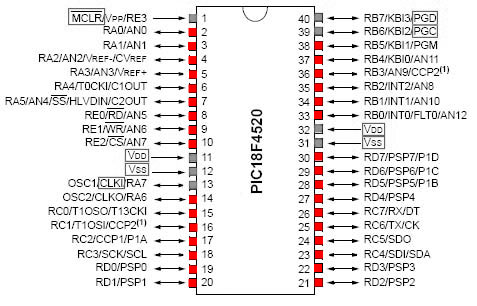
With the exception of the positive voltage supply and ground pins, all pins on the PIC18F4520 can be used as digital I/O, however a few other pins (shown in grey below) are commonly utilized for communication instead of digital I/O. |
With the exception of the positive voltage supply and ground pins, all pins on the PIC18F4520 can be used as digital I/O, however a few other pins (shown in grey below) are commonly utilized for communication instead of digital I/O. |
||
| Line 5: | Line 6: | ||
==Digital Outputs Example== |
==Digital Outputs Example== |
||
This section uses an example to describe how to setup and write digital outputs using a PIC18F4520. |
|||
===Sample Code=== |
===Sample Code=== |
||
Program to blink one LED on and off every half second. |
Program to blink one LED on and off every half second. |
||
First include header file with definitions for specific PIC. |
First include header file with definitions for specific PIC. |
||
Set fuses. HS is type of external clock, low voltage |
Set fuses. HS is type of external clock, low voltage programming |
||
(LVP) is off, and the watchdog timer (WDT) is off. |
(LVP) is off, and the watchdog timer (WDT) is off. |
||
External clock frequency of 20 MHz is specified. |
External clock frequency of 20 MHz is specified. |
||
| Line 41: | Line 43: | ||
delay_ms(500);} |
delay_ms(500);} |
||
} |
} |
||
===Circuit Diagram=== |
===Circuit Diagram=== |
||
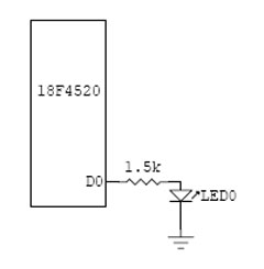
[[Image:digitaloutckt.jpg]] |
[[Image:digitaloutckt.jpg]] |
||
==Digital Output Ports Example== |
==Digital Output Ports Example== |
||
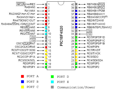
The PIC18F4520 has digital I/O pins organized into five ports. Ports A-D consist of eight pins each, while Port E has only three, although some of these pins are primarily used for communication. The diagram below shows the layout of the different ports on the PIC18F4520 microcontroller. |
|||
<br><br> |
|||
[[Image:4520pindiagramdigitalports.jpg|center]] |
|||
===Sample Code=== |
===Sample Code=== |
||
Program to count in binary from 0-7 and display on LEDs. |
|||
First include header file with definitions for specific PIC. |
|||
Set fuses. HS is type of external clock, low voltage programming |
|||
(LVP) is off, and the watchdog timer (WDT) is off. |
|||
External clock frequency of 20 MHz is specified. |
|||
#include <18f4520.h> |
|||
#fuses HS,NOLVP,NOWDT |
|||
#use delay (clock=20000000) |
|||
Define variables to be used in main program. Both are defined as |
|||
8-bit numbers, with count already being assigned a value while temp |
|||
is left unassigned. |
|||
int count = 0; |
|||
int temp; |
|||
Begin main body of program. |
|||
void main(void) { |
|||
Set Port D to be an output (0). The SET_TRIS_X function can also be |
|||
used to set ports to be inputs (1). |
|||
SET_TRIS_D(0); |
|||
Use while to create an infinite loop. |
|||
while(TRUE){ |
|||
Assign the value of "count" to Port D, thus displaying it on |
|||
the LEDs connected to Port D. |
|||
OUTPUT_D(count); |
|||
delay_ms(500); |
|||
Check the value of "count", and either increment it or reset it |
|||
to zero. |
|||
if(count<7){ |
|||
++count;} |
|||
else { |
|||
count = 0;} |
|||
} |
|||
} |
|||
===Circuit Diagram=== |
===Circuit Diagram=== |
||
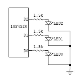
[[Image:Digitaloutportckt.jpg]] |
|||
Latest revision as of 08:23, 5 July 2007
Working with digital inputs and outputs is fundamental to circuit design, and PIC microcontrollers add versatility to design by allowing programming and re-programming of the logic associated with input and output pins. In this way, one PIC microcontroller can take the place of many pre-programmed digital logic ICs.
Available Pins
With the exception of the positive voltage supply and ground pins, all pins on the PIC18F4520 can be used as digital I/O, however a few other pins (shown in grey below) are commonly utilized for communication instead of digital I/O.
Digital Outputs Example
This section uses an example to describe how to setup and write digital outputs using a PIC18F4520.
Sample Code
Program to blink one LED on and off every half second.
First include header file with definitions for specific PIC. Set fuses. HS is type of external clock, low voltage programming (LVP) is off, and the watchdog timer (WDT) is off. External clock frequency of 20 MHz is specified.
  #include <18f4520.h>
  #fuses HS,NOLVP,NOWDT
  #use delay (clock=20000000)
Define pin names to be used in the main program. See header file for currently defined pin names.
#define LED_0 PIN_C0
Begin main body of program. Notice main is a function of "void". This is a more explicit way of saying main is a function of nothing. Using main() is equivalent. Every program is required to have a function called "main".
void main(void) {
Setup an infinite loop, using a while statement.
while(TRUE){
Turn LED on and off by setting its pin low or high, with a delay between each switching.
        output_low(LED_0);
        delay_ms(500);
        output_high(LED_0);
        delay_ms(500);}
  }
Circuit Diagram
Digital Output Ports Example
The PIC18F4520 has digital I/O pins organized into five ports. Ports A-D consist of eight pins each, while Port E has only three, although some of these pins are primarily used for communication. The diagram below shows the layout of the different ports on the PIC18F4520 microcontroller.
Sample Code
Program to count in binary from 0-7 and display on LEDs.
First include header file with definitions for specific PIC. Set fuses. HS is type of external clock, low voltage programming (LVP) is off, and the watchdog timer (WDT) is off. External clock frequency of 20 MHz is specified.
  #include <18f4520.h>
  #fuses HS,NOLVP,NOWDT
  #use delay (clock=20000000)
Define variables to be used in main program. Both are defined as 8-bit numbers, with count already being assigned a value while temp is left unassigned.
  int count = 0;
  int temp;
Begin main body of program.
void main(void) {
Set Port D to be an output (0). The SET_TRIS_X function can also be used to set ports to be inputs (1).
SET_TRIS_D(0);
Use while to create an infinite loop.
while(TRUE){
Assign the value of "count" to Port D, thus displaying it on the LEDs connected to Port D.
        OUTPUT_D(count);
        delay_ms(500);
Check the value of "count", and either increment it or reset it to zero.
        if(count<7){
           ++count;}
        else {
           count = 0;}
     }
  }


