Difference between revisions of "Optointerrupter"
m (→Program) |
|||
| (23 intermediate revisions by 4 users not shown) | |||
| Line 1: | Line 1: | ||
[[Category:Sensors]] |
[[Category:Sensors]] |
||
==Overview== |
|||
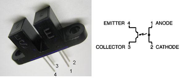
An infrared slotted optical switch is a device similar to the photo-reflector except that the emitter is pointed directly into the phototransistor. The slotted optical switch can be used to build ''shaft encoders''. Shaft encoders can give the robot feedback on how far its wheels have turned or on synchronizing two wheels' velocity. A shaft encoder usually consists of a slotted optical switch and a striped wheel with a palette of radically alternating holes or slots on it. The palette of stripes will alternately reflect or not reflect light to the phototransistor, yielding a pulse-train output. The robot can then tell how far its wheels have rotated by counting the pulses. |
An infrared slotted optical switch is a device similar to the photo-reflector except that the emitter is pointed directly into the phototransistor. The slotted optical switch can be used to build ''shaft encoders''. Shaft encoders can give the robot feedback on how far its wheels have turned or on synchronizing two wheels' velocity. A shaft encoder usually consists of a slotted optical switch and a striped wheel with a palette of radically alternating holes or slots on it. The palette of stripes will alternately reflect or not reflect light to the phototransistor, yielding a pulse-train output. The robot can then tell how far its wheels have rotated by counting the pulses. '''(When using the optointerrupter, make sure that the object that interrupts the beam can completely block an infrared beam. Don't use a thin white piece of paper, which allows light to pass through.)''' |
||
[[image:optointerrupter.png|center|600px]] |
[[image:optointerrupter.png|center|600px]] |
||
| ⚫ | |||
===Circuitry=== |
===Circuitry=== |
||
An example circuit (that should work with the PC104 stack's digital input) for the QVB 11134 slotted optical switch is shown below. When nothing obstructs the infrared beam, the phototransistor conducts and holds the voltage low. When the beam is broken, the phototransistor no longer conducts, and the voltage goes high. Because the |
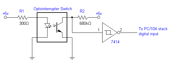
An example circuit (that should work with the PC104 stack's digital input) for the QVB 11134 slotted optical switch is shown below. When nothing obstructs the infrared beam, the phototransistor conducts and holds the voltage low. When the beam is broken, the phototransistor no longer conducts, and the voltage goes high. Because the phototransistor still has significant impedance when it is conducting, we use a large resistor (R2) to limit the current so the voltage will be close to zero when the beam is unbroken. We use a [[Schmitt_Trigger|Schmitt trigger]] to buffer our signal and inject hysteresis to prevent jitter on the output signal. Remember to add a resistor (R1) to protect the IR LED in the switch. |
||
[[image: |
[[image:optointerrupter_ex_schematic.png]] |
||
[[image: |
[[image:optointerrupter_ex_photo1.jpg| 400 px]] |
||
[[image:optointerrupter_ex_photo2.jpg| 400 px]] |
|||
| ⚫ | |||
[[image:optointerrupter_ex_photo3.jpg | 400 px]] |
|||
| ⚫ | |||
| ⚫ | The files below contain an example XPC Target program that will count the number of times the IR beam has been broken, and [[Using_RS-232_and_Printing_to_LCD |display them on the Seetron BPI-216 LCD display]] (on the COM1 serial port). Connect the output of the circuit above to ''channel 2'' of the PC104 stack's digital input port. Depressing the ''Bit1'' button (which sets ''channel 1'' high) on the stack's break-out board will reset the counter to 0. Of course, you can edit the Simulink model to tweak the settings or route the data elsewhere |
||
| ⚫ | |||
[[Media:optointerruptor_XPC_program.zip]] |
|||
===Alternative Circuitry=== |
|||
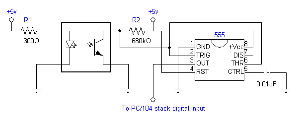
If you are having problems with jitter, you can consider trying the alternative circuit below, which uses a 555 timer instead of a Schmitt trigger. |
|||
[[Image:optointerrupter_555_circuit_schematic.png]] |
|||
===Program=== |
|||
| ⚫ | The files below contain an example XPC Target program that will count the number of times the IR beam has been broken, and [[Using_RS-232_and_Printing_to_LCD |display them on the Seetron BPI-216 LCD display]] (on the COM1 serial port). Connect the output of the circuit above to ''channel 2'' of the PC104 stack's digital input port. Depressing the ''Bit1'' button (which sets ''channel 1'' high) on the stack's break-out board will reset the counter to 0. Of course, you can edit the Simulink model to tweak the settings or route the data elsewhere. |
||
[[Media:optointerrupter_XPC_program.zip|optointerrupter_XPC_program.zip]] |
|||
Unzip both files into your work directory, and open the .mdl file. |
|||
[[Image:optointerrupter_XPC.png ]] |
|||
Latest revision as of 19:08, 20 August 2006
Overview
An infrared slotted optical switch is a device similar to the photo-reflector except that the emitter is pointed directly into the phototransistor. The slotted optical switch can be used to build shaft encoders. Shaft encoders can give the robot feedback on how far its wheels have turned or on synchronizing two wheels' velocity. A shaft encoder usually consists of a slotted optical switch and a striped wheel with a palette of radically alternating holes or slots on it. The palette of stripes will alternately reflect or not reflect light to the phototransistor, yielding a pulse-train output. The robot can then tell how far its wheels have rotated by counting the pulses. (When using the optointerrupter, make sure that the object that interrupts the beam can completely block an infrared beam. Don't use a thin white piece of paper, which allows light to pass through.)
Using with PC/104 Stack
Circuitry
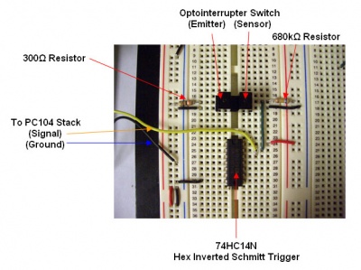
An example circuit (that should work with the PC104 stack's digital input) for the QVB 11134 slotted optical switch is shown below. When nothing obstructs the infrared beam, the phototransistor conducts and holds the voltage low. When the beam is broken, the phototransistor no longer conducts, and the voltage goes high. Because the phototransistor still has significant impedance when it is conducting, we use a large resistor (R2) to limit the current so the voltage will be close to zero when the beam is unbroken. We use a Schmitt trigger to buffer our signal and inject hysteresis to prevent jitter on the output signal. Remember to add a resistor (R1) to protect the IR LED in the switch.
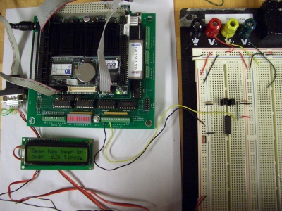
(Note: the mounting tabs on the QVB 11134 optical switch have been snipped off to not obstruct the components on the breadbord.)
Alternative Circuitry
If you are having problems with jitter, you can consider trying the alternative circuit below, which uses a 555 timer instead of a Schmitt trigger.
Program
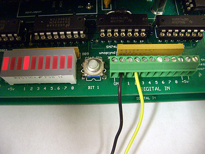
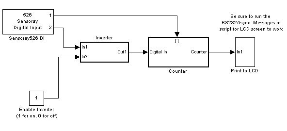
The files below contain an example XPC Target program that will count the number of times the IR beam has been broken, and display them on the Seetron BPI-216 LCD display (on the COM1 serial port). Connect the output of the circuit above to channel 2 of the PC104 stack's digital input port. Depressing the Bit1 button (which sets channel 1 high) on the stack's break-out board will reset the counter to 0. Of course, you can edit the Simulink model to tweak the settings or route the data elsewhere.
optointerrupter_XPC_program.zip
Unzip both files into your work directory, and open the .mdl file.
