Difference between revisions of "Passive Filters"
| (14 intermediate revisions by the same user not shown) | |||
| Line 1: | Line 1: | ||
__TOC__ |
__TOC__ |
||
We can build some very simple filters out of a capacitor and a resistor. A filter |
We can build some very simple filters out of a capacitor and a resistor. A filter blocks some frequencies, while admitting others. |
||
Better filters can be made out of op-amps. |
|||
==Low-Pass Filters (LPF)== |
==Low-Pass Filters (LPF)== |
||
A low |
A low-pass filter admits lower frequencies and blocks out high ones. This can help us smooth out our signals and get rid of high frequency noise. |
||
We can make one by hooking up our capacitor and resistor like this: |
We can make one by hooking up our capacitor and resistor like this: |
||
[[Image:RC_LPF_schematic. |
[[Image:RC_LPF_schematic.gif]] |
||
When set R=500 |
When set R=500Ω and C=2nF, and hook up an AC voltage source, the voltage we see at <math>V_out</math> depends on the frequency of our source. Here is a plot of the magnitude response of the filter, on a logarithmic scale from 10Hz to 10MHz: |
||
[[Image: |
[[Image:RC_LPF_magnitude_response.gif]] |
||
Here are plots comparing the input and output voltages for two different frequencies: |
|||
| ⚫ | |||
[[Image:RC_LPF_freq_compare.gif]] |
|||
| ⚫ | |||
| ⚫ | |||
| ⚫ | |||
| ⚫ | |||
| ⚫ | |||
| ⚫ | |||
| ⚫ | |||
| ⚫ | |||
| ⚫ | |||
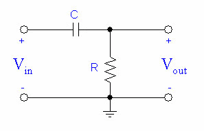
We can make a simple high-pass filter by hooking up our capacitor and resistor like this: |
We can make a simple high-pass filter by hooking up our capacitor and resistor like this: |
||
[[Image:RC_HPF_schematic. |
[[Image:RC_HPF_schematic.gif]] |
||
The |
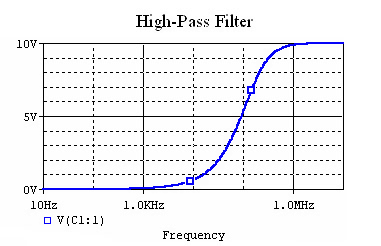
The magnitude response of a filter with R=500Ω and C=2nF looks like this: |
||
[[Image: |
[[Image:RC_HPF_magnitude_Response.gif]] |
||
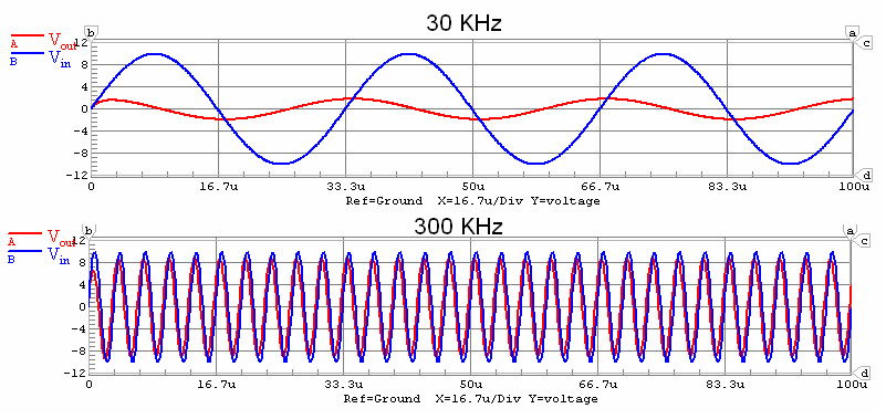
Here are some plots comparing the input and output voltages for two different frequencies: |
|||
[[Image:RC_HPF_freq_compare.gif]] |
|||
This time, the filter blocks the lower frequencies. |
This time, the filter blocks the lower frequencies. |
||
| Line 34: | Line 44: | ||
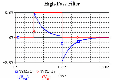
When we put a square wave though the filter, the resulting waveform looks like this: |
When we put a square wave though the filter, the resulting waveform looks like this: |
||
[[Image:RC_HPF_square_wave. |
[[Image:RC_HPF_square_wave.gif]](C=200uF, R=500Ω) |
||
Notice that when the input voltage drops to zero, the output voltage becomes negative. This is because the capacitor is discharging, and forcing the current backwards. |
Notice that when the input voltage drops to zero, the output voltage becomes negative. This is because the capacitor is discharging, and forcing the current backwards. |
||
==References== |
|||
Hayt, William H. Jr., Jack E. Kemmerly, and Steven M. Durbin. <u>Engineering Circuit Analysis</u>. 6th ed. New York:McGraw-Hill, 2002. |
|||
Latest revision as of 15:45, 6 July 2006
We can build some very simple filters out of a capacitor and a resistor. A filter blocks some frequencies, while admitting others.
Better filters can be made out of op-amps.
Low-Pass Filters (LPF)
A low-pass filter admits lower frequencies and blocks out high ones. This can help us smooth out our signals and get rid of high frequency noise.
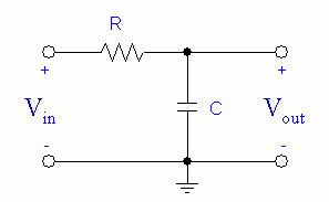
We can make one by hooking up our capacitor and resistor like this:
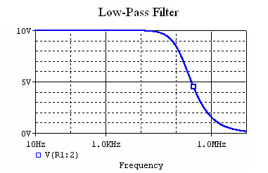
When set R=500Ω and C=2nF, and hook up an AC voltage source, the voltage we see at depends on the frequency of our source. Here is a plot of the magnitude response of the filter, on a logarithmic scale from 10Hz to 10MHz:
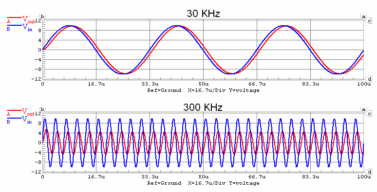
Here are plots comparing the input and output voltages for two different frequencies:
As we can see, the filter blocks the higher frequencies.
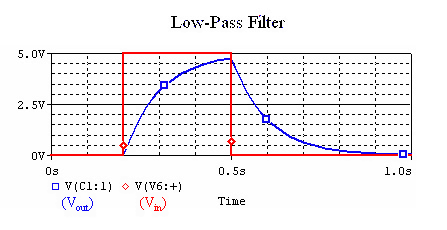
A square wave is made out of a superposition of many sine waves, the low-pass filter blocks out the sine waves with higher frequencies. Our input and output looks like:
High-Pass Filter (HPF)
A high-pass filter blocks out lower frequencies while letting high frequencies through. The output signal responds more strongly to changes in the input signal, such as that coming from a motion detector.
We can make a simple high-pass filter by hooking up our capacitor and resistor like this:
The magnitude response of a filter with R=500Ω and C=2nF looks like this:
Here are some plots comparing the input and output voltages for two different frequencies:
This time, the filter blocks the lower frequencies.
When we put a square wave though the filter, the resulting waveform looks like this:
Notice that when the input voltage drops to zero, the output voltage becomes negative. This is because the capacitor is discharging, and forcing the current backwards.
References
Hayt, William H. Jr., Jack E. Kemmerly, and Steven M. Durbin. Engineering Circuit Analysis. 6th ed. New York:McGraw-Hill, 2002.
