Difference between revisions of "Rock Paper Scissors Machine"
| (21 intermediate revisions by the same user not shown) | |||
| Line 1: | Line 1: | ||
==Overview== |
==Overview== |
||
[[ |
[[Image:rps_whole_thing.JPG|thumb|250px|Entire assembly|right]] |
||
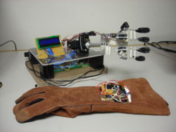
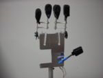
We have created a machine that will play a fully functioning, intuitive game of [http://en.wikipedia.org/wiki/Rock-paper-scissors Rock/Paper/Scissors] (abbreviated as RPS) with a user. The machine is represented by a human-like hand, capable of seperate and independant wrist, arm, finger and thumb motion. The players' hand goes into a glove equipped with flex sensors, which wirelessly transmits data to the machine based on what the player chose. The machine then reads this data, randomly chooses a throw of its own, and displays win/loss/tie both on an [http://en.wikipedia.org/wiki/Lcd LCD] screen and in the form of a thumbs up/down/side motion.<br><br><br><br><br><br><br> |
We have created a machine that will play a fully functioning, intuitive game of [http://en.wikipedia.org/wiki/Rock-paper-scissors Rock/Paper/Scissors] (abbreviated as RPS) with a user. The machine is represented by a human-like hand, capable of seperate and independant wrist, arm, finger and thumb motion. The players' hand goes into a glove equipped with flex sensors, which wirelessly transmits data to the machine based on what the player chose. The machine then reads this data, randomly chooses a throw of its own, and displays what the machine threw, what the human threw, total win/loss/tie info, and winner/loser both on an [http://en.wikipedia.org/wiki/Lcd LCD] screen and in the form of a thumbs up/down/side motion. Video of the machine in action can be found [http://www.youtube.com/watch?v=xbLNBSTTrcE here.]<br><br><br><br><br><br><br><br><br> |
||
==Team Members== |
==Team Members== |
||
[[Image:rps team.JPG|thumb|250px|Reed playing against the machine|right]] |
[[Image:rps team.JPG|thumb|250px|Reed playing against the machine|right]] |
||
[[Image:Rps_team2.jpg|thumb|250px|Entire team|left]] |
|||
Chris Carhart - Mechanical Engineer 2010<br> |
Chris Carhart - Mechanical Engineer 2010<br> |
||
Kevin Kao - Mechanical Engineer 2010<br> |
Kevin Kao - Mechanical Engineer 2010<br> |
||
Reed Walker - Electrical Engineer 2009<br> |
Reed Walker - Electrical Engineer 2009<br> |
||
<br><br><br><br><br><br><br><br> |
<br><br><br><br><br><br><br><br><br> |
||
==The Players' Glove== |
==The Players' Glove== |
||
[[Image:rps glove.JPG|thumb|250px|The player's glove|right]] |
[[Image:rps glove.JPG|thumb|250px|The player's glove|right]] |
||
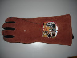
The players' glove is a large, leather grill glove with a wireless RF transmitter and two flex sensors embedded inside, one on the index finger, and one on the ring finger. We assumed, reasonably, that the three throws could be determined by the position of the index and ring fingers alone. It also has a power light and an on/off switch. The goal was to have it easily used by everyone, and high percentage success rate of transmitting the throw the user chooses. |
The players' glove is a large, leather grill glove with a wireless RF transmitter and two flex sensors embedded inside, one on the index finger, and one on the ring finger. We assumed, reasonably, that the three throws could be determined by the position of the index and ring fingers alone. It also has a power light and an on/off switch. The goal was to have it easily used by everyone, and high percentage success rate of transmitting the throw the user chooses. |
||
==== |
====Wireless capability==== |
||
The human user simply has to slide on a glove, and play RPS as normal in order to interact with the computer. The glove takes care of all of the electronics and uses wireless transmission to send data to the PIC. In the mind of the user, the design should be as intuitive as possible and create no confusion. The glove is created this way. |
|||
i dunno anything about this actually |
|||
The PIC will first send a signal to the LCD screen to indicate that the computer is ready to play. The LCD screen will display "flip the red switch on the glove to begin." The user will put the glove on, flip the switch and the game will begin. "Rock, Paper, Scissors, SHOOT!" On the SHOOT signal, the computer will make a hand gesture as should the human. If the human does not make a 'rock', 'paper, or 'scissors' gesture, the computer will get confused, and possibly read the human signal as something else, so the human needs to be sure the make actual RPS hand gestures (as in a normal RPS game). |
|||
The computer will read the human's gesture, compare it to its own, and decide who the victor is. The victor will be recorded in the computer's memory, and the game will continue. So how does the glove work? |
|||
====High Level Operation==== |
|||
The glove is a two layered leather/cotton glove with the cotton as the inside layer. We made an incision in the glove to access the space between the layers. Inside the glove are all of the electronics that allow the glove to read a RPS signal and transmit wirelessly to the PIC. Inside the index finger and the ring finger of the right hand glove are two flex resistors (see below for a more detailed description). Since there are only three options in RPS, the game only requires two bits – hence two flex resistors. In the game of RPS, the only hand gesture that has a bend index finger is the ROCK. If the flex resistor inside of the index finger is bent, then the system knows that the human is making a ROCK gesture. The only gesture that has the ring finger bent that the index finger straight is the SCISSORS gesture. Similarly, the only gesture with those two fingers unbent, is the PAPER gesture. In this way, we were able to digitally send a two bit signal from the glove to the PIC. |
|||
====Detailed Description of Glove Operation==== |
|||
A flow chart to sequence the glove’s many operations is shown to the right. A detailed description of each step follows. |
|||
[[Image:Rps glove diagram.PNG|left|Glove operation diagram]] |
|||
<br><br><br><br><br><br><br><br><br><br><br><br> |
|||
[[Image:Rps_flex_sensor.png|thumb|250px|right|Source: http://www.ecs.umass.edu/ece/m5/images/Flex_Sensor_With_Header_L.jpg]] |
|||
====Fingers==== |
|||
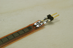
Inside of the fingers of the glove are flex resistors as shown to the right. These are what the resistors inside of the glove’s index and ring finger look like. |
|||
These flex resistors act like a normal resistor with a voltage across it. The difference is that if this resistor is bent the resistance actually changes. Bending in one direction from the resting position, causes the resistance to decrease and bending in the other direction causes the resistance to increase. The range of resistances is as follows: |
|||
Max: 50 kOhms<br> |
|||
Default: 11 kOhms<br> |
|||
Min: 6 kOhms<br> |
|||
<br><br><br><Br><br><br> |
|||
The difference between the default and max resistance was found bending the flex resistor in the direction as indicated to the right. |
|||
[[Image:Rps_flex_sensor_2.png|thumb|250px|right|Source: http://www.ecs.umass.edu/ece/m5/images/Flex_Sensor_Full_Flex_L.jpg]] |
|||
We oriented the flex resistors such that when the human bends his/her fingers, the resistor bends in this direction causing maximum differentiation in resistance between bent and unbent finger. The flex resistors are placed between two layers of the glove so that the human does not notice the resistors next to his/her fingers. |
|||
There are two flex resistors inside of the glove as described above. One resistor corresponds to the human index finger, and the other one corresponds to the ring finger. For a high level description of how the bending of fingers leads to an operation game, see above. |
|||
[http://www.sensorwiki.org/doku.php/sensors/flexion Flex sensors] are used to tell what throw the player chose. Flex sensors have a varying resistance based on the bend of the sensor - a higher bend angle means higher resistance value. A high bend angle (>60 degrees or so) will have a resistance high enough so that the RC reader reads a low signal. |
|||
*If the player throws rock, both flex sensors will be bent, and the read resistances will be high |
|||
*If the player throws scissors, the ring finger flex sensor will be bent, but the index finger's sensor will not. |
|||
*If the player throws paper, neither of the flex sensors will be bent. |
|||
These three combinations are enough to send three unique signals to the PIC. |
|||
<br><Br><br><br> |
|||
====Flex sensors==== |
====Flex sensors==== |
||
[http://www.sensorwiki.org/doku.php/sensors/flexion Flex sensors] are used to tell what throw the player chose. Flex sensors have a varying resistance based on the bend of the sensor - a higher bend angle means higher resistance value. A high bend angle (>60 degrees or so) will have a resistance high enough so that the RC reader reads a low signal. |
[http://www.sensorwiki.org/doku.php/sensors/flexion Flex sensors] are used to tell what throw the player chose. Flex sensors have a varying resistance based on the bend of the sensor - a higher bend angle means higher resistance value. A high bend angle (>60 degrees or so) will have a resistance high enough so that the RC reader reads a low signal. |
||
| Line 21: | Line 55: | ||
*If the player throws paper, neither of the flex sensors will be bent. |
*If the player throws paper, neither of the flex sensors will be bent. |
||
These three combinations are enough to send three unique signals to the PIC. |
These three combinations are enough to send three unique signals to the PIC. |
||
====Analog to digital conversion==== |
|||
[[Image:Rps voltage divider.png|thumb|250px|Flex resistor is R1,R2 is 6.8 kOhms|right]] |
|||
Inside of the glove is an analog to digital converter to convert the signal from the flex resistor into a digital signal that could be sent to the PIC. The first step is to know the resistance range of the flex resistors. As indicated above, when the finger is unbent, the resistance is about 11 kOhms. On average, when the finger is bent, the resistance is around 30 kOhms. These flex resistors are placed in series with a stable resistors (6.8 kOhms). The flex resistor and the stable resistor will act as a voltage divider as seen on the right. |
|||
The Vin being used within the glove is 9v. R1, in this case, is the variable flex resistor. The voltage output from an unbent finger is thus about 3.4v. The voltage output from a bent finger is thus about 1.66v. Since this voltage swing is sufficiently large, we sent the signal into both inputs of an AND gate. We used the Jameco 74HC08 Quad 2-Input AND gate. Since the 3.4v and 1.66v were above and below the threshold values of this AND gate, the output of the AND gate would be high when a finger is unbent and low when a finger is bent. Since we are powering the glove with 9v, we used another voltage divider to drop the 9v to 5v to power the AND gate. A picture of the circuit can be found on the right. |
|||
[[Image:Rps_transmitter.JPG|thumb|200px|Reciever|right]] |
|||
<br><br><br><Br><br><br><br><Br><br><br><Br><br><br><br><br><br><Br><br><br><br><br><br><Br><br> |
|||
Using this method, we were successful in digitizing a signal from the fingers. This table summarizes the inputs and outputs of the system. |
|||
[[Image:Rps voltage table.png|thumb|350px|Inputs and Outputs|left]] |
|||
<br><br><br><Br><br><br><br><Br><br><br><Br><br><br><br> |
|||
====Digital to serial conversion and RF transmission==== |
|||
Once we had the digital signal it needed to be converted to a serial signal to then be transmitted via radio frequency to the receiver next to the PIC. Instead of buying the necessary integrated circuit and constructing the circuit from scratch, we reverse engineered an RC car (as pictured to the right). |
|||
The transmission circuit itself is quite simple. It is basically one IC with 14 pins that connect to power, some capacitors/resistors (for tuning), and the inputs and output. The output is then sent to an inductor circuit that goes to a long wire to transmit the signal. The inductor circuit is also simple and help can be found in Stan Gibilisco’s book “Teach Yourself Electricity and Electronics.” Basically though, in RF transmission, “coils are routinely connected in series or parallel with capacitors to obtain tuned circuits” (Gibilsco, pg. 169). The IC being used is a SUPERCHIP SCTX2B and can be found here: http://pdf1.alldatasheet.com/datasheet-pdf/view/113422/ETC/SCTX2B.html It is written in Chinese. An English version could not be found. The pins to the chip can still be read, but it may be helpful to confirm with either your fellow Cantonese/Mandarin speaking friend or call the help line at the top of the page. The best method to get a wireless RF solution though, is probably just buy a cheap remote control car. |
|||
[[Image:Rps_rc_car.png|thumb|250px|right|Source: http://hackedgadgets.com/wp-content/2/_rc_car_autonomous_drifting_hack_2.jpg]] |
|||
The remote transmitted, and the car received two pieces of information: Turn from wheels left or right, and spin back wheels front or back. This device was all or nothing – meaning, there was no variable speed or variable turning radius (in other words, buy the least expensive toy car you can). We took apart the car and remote control and used the circuits within. The bits that corresponded to the back wheels spinning we used for the button on the glove that indicated whether or not the human was ready to play the game or not (the red switch on the glove that powered the glove as well as send a signal to the PIC indicating that the human is ready to play). The bits that corresponded to the front wheels turning we used to indicate the nature of the glove’s (un)bent fingers. The following table summarizes some of the remote control’s signals. |
|||
[[Image:Rps rc table.png|thumb|250px|left|Input voltages on RC]] |
|||
<br><br><br><Br><br><br><br><Br><br> |
|||
Notice how these voltages correspond exactly to the voltages that the hand gestures made. The reason why there are two assignments for ROCK we did not want to leave a bit sequence unassigned and the remote control reads 0v,0v the same as 0v,5v. This allowed us to send all three potential bit sequences using the existing hardware on the remote control. |
|||
====Decoding the RF transmission and Sending the Signal to the PIC==== |
|||
The decoder circuit next to the PIC essentially does what the encoder/transmitter circuit did in reverse. The IC that is used is instead a 16 pin chip and described on the same datasheet at the one mentioned earlier. Now, in this case, there are four outputs – one corresponding to each of the four commands – turn right, turn left, go forward, go back, but in our case those transmission lines were modified to mean ROCK, SCISSORS, glove on, and nothing - respectively. The default position was of course PAPER. These outputs were then sent to the input pins of the PIC. Pull down resistors were placed as a precautionary measure against ‘floating’ signals from the wireless receiver to the PIC. |
|||
====PIC interpretation of the input signal==== |
|||
This table should be self explanatory. If the PIC received the inputs as indicated on the table, then it would know what hand gesture the human had made. More about the coding can be read in the following sections. |
|||
[[Image:Rps inputs to the pic.png|thumb|250px|left|Inputs to the PIC]] |
|||
<br><br><br><Br><br><br><br><Br><br><br> |
|||
[[Image:Rps pic diagram.PNG|left|PIC input diagram]] |
|||
<br><br><br><Br><br><br><br><Br><br><Br><br><br> |
|||
====RF System Flaws and Recommendations==== |
|||
We would not suggest using a RF solution. A better solution would be Xbee communication between two pics as covered extensively on this wiki. The RF solution was very inconsistent. The range was sometimes great but more often than not, the range was only a few feet. Extending the antenna helped, but only mildly. Also, if the antenna was covered at all, the range seemed to drop down to inches. The solution worked for our project because RPS is played in close proximity. Hacking a more expensive remote control car or other RF device might work, but then one has more of an incentive to use the Xbee solution. The Xbee solution is inexpensive, consistent, and easy to use thanks to the accompanying [[XBee radio communication between PICs|wiki-page]]. |
|||
====Other Glove Features==== |
====Other Glove Features==== |
||
The power switch can turn the game on or off. In the off position, the PIC will display a blank screen until the glove is turned back on. |
The power switch can turn the game on or off. In the off position, the PIC will display a blank screen until the glove is turned back on. |
||
| Line 50: | Line 123: | ||
==The Stand== |
==The Stand== |
||
The machine stand consists of a wooden base and an acrylic top layer, separated by 4 wooden pillars. The arm is mounted to the acrylic as is the LCD display using a propped up circuit board and bracket. All of the remaining electronics are housed in the space between the acrylic and the wooden base. This protects the fragile electronics (PIC board, receiver, wires, etc.) but lets us still check on things if necessary. |
The machine stand consists of a wooden base and an acrylic top layer, separated by 4 wooden pillars. The arm is mounted to the acrylic as is the LCD display using a propped up circuit board and bracket. All of the remaining electronics are housed in the space between the acrylic and the wooden base. This protects the fragile electronics (PIC board, receiver, wires, etc.) but lets us still check on things if necessary. |
||
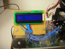
====Typical LCD Output During A Game==== |
|||
[[Image:rps lcd.JPG|thumb|250px|The LCD screen|right]] |
|||
*ROCK! |
|||
*PAPER! |
|||
*SCISSORS! |
|||
*SHOOT! |
|||
*MACHINE: ROCK |
|||
*HUMAN: PAPER |
|||
*YOU WIN! |
|||
*(WIN-LOSS-TIE) = (2-4-1) |
|||
(this repeats endlessly) |
|||
==Code== |
==Code== |
||
Latest revision as of 22:59, 19 March 2009
Overview
We have created a machine that will play a fully functioning, intuitive game of Rock/Paper/Scissors (abbreviated as RPS) with a user. The machine is represented by a human-like hand, capable of seperate and independant wrist, arm, finger and thumb motion. The players' hand goes into a glove equipped with flex sensors, which wirelessly transmits data to the machine based on what the player chose. The machine then reads this data, randomly chooses a throw of its own, and displays what the machine threw, what the human threw, total win/loss/tie info, and winner/loser both on an LCD screen and in the form of a thumbs up/down/side motion. Video of the machine in action can be found here.
Team Members
Chris Carhart - Mechanical Engineer 2010
Kevin Kao - Mechanical Engineer 2010
Reed Walker - Electrical Engineer 2009
The Players' Glove
The players' glove is a large, leather grill glove with a wireless RF transmitter and two flex sensors embedded inside, one on the index finger, and one on the ring finger. We assumed, reasonably, that the three throws could be determined by the position of the index and ring fingers alone. It also has a power light and an on/off switch. The goal was to have it easily used by everyone, and high percentage success rate of transmitting the throw the user chooses.
Wireless capability
The human user simply has to slide on a glove, and play RPS as normal in order to interact with the computer. The glove takes care of all of the electronics and uses wireless transmission to send data to the PIC. In the mind of the user, the design should be as intuitive as possible and create no confusion. The glove is created this way.
The PIC will first send a signal to the LCD screen to indicate that the computer is ready to play. The LCD screen will display "flip the red switch on the glove to begin." The user will put the glove on, flip the switch and the game will begin. "Rock, Paper, Scissors, SHOOT!" On the SHOOT signal, the computer will make a hand gesture as should the human. If the human does not make a 'rock', 'paper, or 'scissors' gesture, the computer will get confused, and possibly read the human signal as something else, so the human needs to be sure the make actual RPS hand gestures (as in a normal RPS game).
The computer will read the human's gesture, compare it to its own, and decide who the victor is. The victor will be recorded in the computer's memory, and the game will continue. So how does the glove work?
High Level Operation
The glove is a two layered leather/cotton glove with the cotton as the inside layer. We made an incision in the glove to access the space between the layers. Inside the glove are all of the electronics that allow the glove to read a RPS signal and transmit wirelessly to the PIC. Inside the index finger and the ring finger of the right hand glove are two flex resistors (see below for a more detailed description). Since there are only three options in RPS, the game only requires two bits – hence two flex resistors. In the game of RPS, the only hand gesture that has a bend index finger is the ROCK. If the flex resistor inside of the index finger is bent, then the system knows that the human is making a ROCK gesture. The only gesture that has the ring finger bent that the index finger straight is the SCISSORS gesture. Similarly, the only gesture with those two fingers unbent, is the PAPER gesture. In this way, we were able to digitally send a two bit signal from the glove to the PIC.
Detailed Description of Glove Operation
A flow chart to sequence the glove’s many operations is shown to the right. A detailed description of each step follows.
Fingers
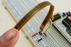
Inside of the fingers of the glove are flex resistors as shown to the right. These are what the resistors inside of the glove’s index and ring finger look like. These flex resistors act like a normal resistor with a voltage across it. The difference is that if this resistor is bent the resistance actually changes. Bending in one direction from the resting position, causes the resistance to decrease and bending in the other direction causes the resistance to increase. The range of resistances is as follows:
Max: 50 kOhms
Default: 11 kOhms
Min: 6 kOhms
The difference between the default and max resistance was found bending the flex resistor in the direction as indicated to the right.
We oriented the flex resistors such that when the human bends his/her fingers, the resistor bends in this direction causing maximum differentiation in resistance between bent and unbent finger. The flex resistors are placed between two layers of the glove so that the human does not notice the resistors next to his/her fingers.
There are two flex resistors inside of the glove as described above. One resistor corresponds to the human index finger, and the other one corresponds to the ring finger. For a high level description of how the bending of fingers leads to an operation game, see above. Flex sensors are used to tell what throw the player chose. Flex sensors have a varying resistance based on the bend of the sensor - a higher bend angle means higher resistance value. A high bend angle (>60 degrees or so) will have a resistance high enough so that the RC reader reads a low signal.
- If the player throws rock, both flex sensors will be bent, and the read resistances will be high
- If the player throws scissors, the ring finger flex sensor will be bent, but the index finger's sensor will not.
- If the player throws paper, neither of the flex sensors will be bent.
These three combinations are enough to send three unique signals to the PIC.
Flex sensors
Flex sensors are used to tell what throw the player chose. Flex sensors have a varying resistance based on the bend of the sensor - a higher bend angle means higher resistance value. A high bend angle (>60 degrees or so) will have a resistance high enough so that the RC reader reads a low signal.
- If the player throws rock, both flex sensors will be bent, and the read resistances will be high
- If the player throws scissors, the ring finger flex sensor will be bent, but the index finger's sensor will not.
- If the player throws paper, neither of the flex sensors will be bent.
These three combinations are enough to send three unique signals to the PIC.
Analog to digital conversion
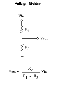
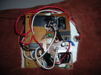
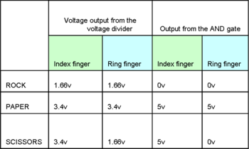
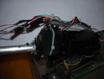
Inside of the glove is an analog to digital converter to convert the signal from the flex resistor into a digital signal that could be sent to the PIC. The first step is to know the resistance range of the flex resistors. As indicated above, when the finger is unbent, the resistance is about 11 kOhms. On average, when the finger is bent, the resistance is around 30 kOhms. These flex resistors are placed in series with a stable resistors (6.8 kOhms). The flex resistor and the stable resistor will act as a voltage divider as seen on the right. The Vin being used within the glove is 9v. R1, in this case, is the variable flex resistor. The voltage output from an unbent finger is thus about 3.4v. The voltage output from a bent finger is thus about 1.66v. Since this voltage swing is sufficiently large, we sent the signal into both inputs of an AND gate. We used the Jameco 74HC08 Quad 2-Input AND gate. Since the 3.4v and 1.66v were above and below the threshold values of this AND gate, the output of the AND gate would be high when a finger is unbent and low when a finger is bent. Since we are powering the glove with 9v, we used another voltage divider to drop the 9v to 5v to power the AND gate. A picture of the circuit can be found on the right.
Using this method, we were successful in digitizing a signal from the fingers. This table summarizes the inputs and outputs of the system.
Digital to serial conversion and RF transmission
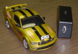
Once we had the digital signal it needed to be converted to a serial signal to then be transmitted via radio frequency to the receiver next to the PIC. Instead of buying the necessary integrated circuit and constructing the circuit from scratch, we reverse engineered an RC car (as pictured to the right).
The transmission circuit itself is quite simple. It is basically one IC with 14 pins that connect to power, some capacitors/resistors (for tuning), and the inputs and output. The output is then sent to an inductor circuit that goes to a long wire to transmit the signal. The inductor circuit is also simple and help can be found in Stan Gibilisco’s book “Teach Yourself Electricity and Electronics.” Basically though, in RF transmission, “coils are routinely connected in series or parallel with capacitors to obtain tuned circuits” (Gibilsco, pg. 169). The IC being used is a SUPERCHIP SCTX2B and can be found here: http://pdf1.alldatasheet.com/datasheet-pdf/view/113422/ETC/SCTX2B.html It is written in Chinese. An English version could not be found. The pins to the chip can still be read, but it may be helpful to confirm with either your fellow Cantonese/Mandarin speaking friend or call the help line at the top of the page. The best method to get a wireless RF solution though, is probably just buy a cheap remote control car.
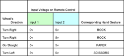
The remote transmitted, and the car received two pieces of information: Turn from wheels left or right, and spin back wheels front or back. This device was all or nothing – meaning, there was no variable speed or variable turning radius (in other words, buy the least expensive toy car you can). We took apart the car and remote control and used the circuits within. The bits that corresponded to the back wheels spinning we used for the button on the glove that indicated whether or not the human was ready to play the game or not (the red switch on the glove that powered the glove as well as send a signal to the PIC indicating that the human is ready to play). The bits that corresponded to the front wheels turning we used to indicate the nature of the glove’s (un)bent fingers. The following table summarizes some of the remote control’s signals.
Notice how these voltages correspond exactly to the voltages that the hand gestures made. The reason why there are two assignments for ROCK we did not want to leave a bit sequence unassigned and the remote control reads 0v,0v the same as 0v,5v. This allowed us to send all three potential bit sequences using the existing hardware on the remote control.
Decoding the RF transmission and Sending the Signal to the PIC
The decoder circuit next to the PIC essentially does what the encoder/transmitter circuit did in reverse. The IC that is used is instead a 16 pin chip and described on the same datasheet at the one mentioned earlier. Now, in this case, there are four outputs – one corresponding to each of the four commands – turn right, turn left, go forward, go back, but in our case those transmission lines were modified to mean ROCK, SCISSORS, glove on, and nothing - respectively. The default position was of course PAPER. These outputs were then sent to the input pins of the PIC. Pull down resistors were placed as a precautionary measure against ‘floating’ signals from the wireless receiver to the PIC.
PIC interpretation of the input signal
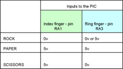
This table should be self explanatory. If the PIC received the inputs as indicated on the table, then it would know what hand gesture the human had made. More about the coding can be read in the following sections.
RF System Flaws and Recommendations
We would not suggest using a RF solution. A better solution would be Xbee communication between two pics as covered extensively on this wiki. The RF solution was very inconsistent. The range was sometimes great but more often than not, the range was only a few feet. Extending the antenna helped, but only mildly. Also, if the antenna was covered at all, the range seemed to drop down to inches. The solution worked for our project because RPS is played in close proximity. Hacking a more expensive remote control car or other RF device might work, but then one has more of an incentive to use the Xbee solution. The Xbee solution is inexpensive, consistent, and easy to use thanks to the accompanying wiki-page.
Other Glove Features
The power switch can turn the game on or off. In the off position, the PIC will display a blank screen until the glove is turned back on. The power light on the glove lets the player know whether the glove is on or off.
The Mechanical Arm
The hand consists of five separate RC servos which all together control arm motion, wrist motion, thumb motion, and finger motion.
The Arm
The base of the arms consists of two Futaba S3004 servos, one for lateral up and down (arm servo) motion and one for axial wrist rotation (wrist servo). The servos are structurally held together with aluminum brackets purchased from lynxmotion.com and the arm is extended with an aluminum tube attached directly to the wrist servo horn, allowing for rotation of the hand. A spring connects the base of the arm servo to base of the wrist servo which stabilizes (and slows) the arm's downward motion as well as reduces the torque needed on the upward swing. The arm servo moves at maximum speed on the downward swing, and at a slightly slower speed on the upward swing, thus mimicking natural RPS motion.
The Wrist
As mentioned above, the wrist motion is created by an aluminum tube and a corresponding servo servo. The tube is mounted with screws to a bracket attached to the arm servo. Its role is to rotate 90 degrees if the PIC chooses Paper, and rotate 0/90/180 degrees for thumbs up/middle/down corresponding to a player's win/tie/loss. For instance if the PIC throws rock and the player throws scissors (player loses), the wrist servo will rotate downwards 180 degrees so the thumb can do a thumbs down.
The Palm
The palm is a sheet metal aluminum bracket designed to mount to the aluminum rod and to support three small servos (one for the thumb and two for the remaining fingers).
The Thumb
The thumb is simply a carbon fiber rod attached to a small servo which is mounted to the palm.
The thumb servo is a Blue Arrow BA-TS-4.3. Its role is to rotate upwards for a player win or loss, and rotate slightly away from the fingers if the PIC throws paper.
The Fingers
The fingers are made up of two brackets. Each bracket consists of two aluminum fingers attached to one another with q-tip shafts and hot glue and each bracket is attached to a small finger servo.
Both finger servos are Blue Arrow BA-TS-9.0s. One servo controls the index and middle fingers, and the other one controls the ring and pinky fingers (ie, index/middle fingers move together, ring/pinky moves together). Both servos default at the rock position. The upper (index and middle fingers) servo rotates about 120 degrees clockwise if the PIC throws scissors. Both servos rotate 120 degrees clockwise if the PIC throws paper.
The Stand
The machine stand consists of a wooden base and an acrylic top layer, separated by 4 wooden pillars. The arm is mounted to the acrylic as is the LCD display using a propped up circuit board and bracket. All of the remaining electronics are housed in the space between the acrylic and the wooden base. This protects the fragile electronics (PIC board, receiver, wires, etc.) but lets us still check on things if necessary.
Typical LCD Output During A Game
- ROCK!
- PAPER!
- SCISSORS!
- SHOOT!
- MACHINE: ROCK
- HUMAN: PAPER
- YOU WIN!
- (WIN-LOSS-TIE) = (2-4-1)
(this repeats endlessly)
Code
The goal of the code was to:
- Separately control 5 different servos
- Read 3 inputs from the player's glove
- Randomly generate a number, and based on that number throw R/P/S
- Display the results on an LCD screen
- Recognize when the player has turned off the glove
Note that the servo control and the random number generator portions were borrowed from the internet.
The outline of the code:
1. Declare constants
2. Interrupts for Servo control
3. Random number generator function
(start of main part of program)
4. Generate a random number
5. Reset arm to default rock position
6. Rotate arm servo 4 times, on the 4th ("shoot"), based on random number, control wrist/fingers to do chosen throw
7. Read and determine what the player threw from the glove
8. Display what the computer threw, what you threw on the LCD, display win or lose
9. Rotate thumb/wrist based on whether the player won or lost
10. Read resistance to see if the glove is turned off. If the glove is turned off do not start game until glove is turned back on
11. Go back to step 4
/*
rps_w_consts.c, k. kao 3/19/2009
*/

#include <18f4520.h>
#device high_ints=TRUE
#DEVICE ADC=10
#fuses HS, NOLVP, NOWDT, NOPROTECT
#use delay(clock=40000000)       // 20 MHz crystal on PCB
#include <lcd_flex.c>

int16 RCservo[6];        // 6 because we need 5 servos
int RCcount;
int i=0;
char x; //used for random integer generation
//all the following constants are specific to our specific servo setup. the ones you use will
//vary based on the starting position, power, and type of the servo used. these constants
//can be changed at will until correct behavior is achieved.
//for our servos, 4999 is the max that can be reached in one direction, and 2300 is the minimum
//for the small finger and thumb servos, where the larger servos have a minimum of about 600.
//the servos will not respond to commmands to move to a position higher/lower than those cutoffs.
int16 resistance1;
int16 resistance3;
int16 res3temp;
int16 resistance5=3000; //resistance 5 (pin A5 here) measures input resistance
int16 old_res5;
int16 new_res5;
int random_byte; //used for random integer generation
int wins=0;
int losses=0;
int ties=0;
int determine = 0;
int index=0;
int ring=0;
int16 upper_high_const = 2300; //upper fingers "paper" constant
int16 upper_low_const = 4999; //upper fingers "rock" constant
int16 lower_high_const = 4899; //lower fingers "paper" constant
int16 lower_low_const = 2300; //lower fingers "rock" constant
int16 wrist_down_const = 199; //wrist "thumbs down" constant
int16 wrist_side_const = 2700; //wrist "paper" constant
int16 wrist_vert_const = 4899; //wrist "rock" constant
int16 thumbs_down_const =2800;//this is actually only used for scissors
int16 thumbs_up_const=4999;
int16 thumbs_mid_const=3700;
int16 thumbs_down_paper_const = 1150; //thumbs down constant for paper
int16 arm_up_const = 2200;
int16 arm_down_const=1000;
int16 res_cutoff = 600;//cutoff resistance for when to start the game
int16 rock_const = 1000;//cutoff for rock
int16 not_rock_const = 1500;//cutoff for not rock, really could be the same as the one above
int16 paper_scissors_const=2500; //over this is scissors, under is paper


//this servo part was borrowed from the wiki and m. peshkin, original comments included

#INT_TIMER2       // designates that this is the routine to call when timer2 overflows
void MyInterruptRoutine() {

   if (++RCcount >= 20) RCcount = 0;         // 20mS cycle;  20 interrupts

   if ((RCcount & 3) == 0) {  // on the 4mS boundaries turn all the pins low
      output_low(PIN_A0);     // comment out the pins you don't want involved
      output_low(PIN_A2);
      output_low(PIN_C5);
      output_low(PIN_C6);
      output_low(PIN_C7);

      set_timer3((int16) 60536 + RCservo[RCcount>>2]);     // yes 60536, not 65536.  Go high 4000uS (5000*0.8uS) from now, and sooner due to desired High period
   }

         // your ISR stuff goes here, after the RC part, so as not to disrupt the timing of turning the servos Low
}

#INT_TIMER3 fast           // "fast" allows Timer 3 to interrupt Timer 2's ISR
void InterruptTimer3() {   // this ISR is called when Timer 3 times out, to set one of the RC servo output pins high
   switch (RCcount>>2) {
      case 0:
         output_high(PIN_A0);     // comment out the pins you don't want involved
         break;

      case 2:
         output_high(PIN_A2);
         break;
      case 3:
         output_high(PIN_C5);
         break;
      case 4:
         output_high(PIN_C6);
         break;
      case 1:
         output_high(PIN_C7);
         break;

   }
}

//random number generator - borrowed from the internet
//any google search will lead you to a random number generator, these are public domain by now
int rand(void)   {
   int sum;
   sum = 0;

   // This calculates parity on the selected bits (mask = 0xb4).
   if(random_byte & 0x80)
      sum = 1;

   if(random_byte & 0x20)
      sum ^= 1;

   if(random_byte & 0x10)
      sum ^= 1;

   if(random_byte & 0x04)
      sum ^= 1;

   random_byte <<= 1;

   random_byte |= sum;

   return(random_byte);
   //printf(lcd_putc, random_byte);
}

void srand(int seed) {
   random_byte = seed;
}

//end of the random number generator

void main() {
lcd_init();
   setup_adc_ports(AN0_TO_AN5);        // Enable analog inputs; choices run from just AN0, up to AN0_TO_AN11
   setup_adc(ADC_CLOCK_INTERNAL);      // the range selected has to start with AN0

   delay_us(10);           // wait 10uS for ADC to settle to a newly selected input
   delay_ms(40);
   setup_timer_2(T2_DIV_BY_4, 77, 16);       // clock at 16KHz; interrupt every 4*50nS * 4 * (77+1) * 16 = 1.0mS
   setup_timer_3(T3_INTERNAL | T3_DIV_BY_4); // Timer 3 is used for the High period for the RC servo signal, ticks every (4*50nS) * 4 = 0.8uS

   enable_interrupts(INT_TIMER3);
   enable_interrupts(INT_TIMER2);
   enable_interrupts(GLOBAL);
   //end of borrowed servo code


   while (TRUE) {
   printf(lcd_putc, "\f "); //clear the lcd
   i=0;
   //this next if statement essentially does this: if I (the computer) has won twice in a row,
   //keep doing one specific throw because it's obviously working.
   if (wins+losses+ties%2>0)
   {
      srand(wins+ties);
   }
   x = rand()%3; //the RNG generates a random number but i only want 3 different numbers so i take its remainder
   //x = 2; activate this and the next line to see if the RNG is working
   // printf(lcd_putc, "%u", x);
         delay_ms(1000);

   while (resistance5 >res_cutoff) //while the switch is off, we want it to display a blank screen
   {
           set_adc_channel(5);
           delay_us(10);
           resistance5 = read_adc();
           //printf(lcd_putc, "\f (%lu)",resistance5); activate these to see what you're reading
           // delay_ms(400);
           printf(lcd_putc, "\f");
           delay_ms(100);
    }

    //the next four commands reset the hand - fingers to "rock position", wrist down, thumb to neutral
      RCservo[4] = upper_high_const;
      RCservo[1] = lower_high_const;
      RCservo[2]=wrist_vert_const;
      RCservo[3]=thumbs_mid_const;

      printf(lcd_putc, "\f(Win-Loss-Tie): \n = (%u-%u-%u)", wins,losses,ties); //display total wins, losses, ties
      delay_ms(2500);  //so the user can read the wins/losses/ties

      while(i<5) //"rock/paper/scissors/shoot" is 4 things so we want it to run 4 times
{
   if (i!=4) //if not on shoot
   {
      RCservo[0]=2700; //arm down but not all the way
   }
   if (i==4) //if it is on shoot put the arm all the way down
   {
      RCservo[0]=3050;
      delay_ms(100);//so the fingers activate on the lower end of the downswing
   }

    if (i==4 && x == 1)//if it's on "shoot" and PIC chooses paper
    {
      RCservo[2]=wrist_side_const; //rotate wrist
      RCservo[4] = upper_low_const;//extend upper fingers
      RCservo[1] = lower_low_const;//extend lower fingers
      RCservo[3] = thumbs_up_const;//extend thumb
    }
        if (i==4 && x == 2)//if its on "shoot" and PIC chooses scissors
    {
      RCservo[4] = upper_low_const; //extend upper fingers
      RCservo[3] = thumbs_down_const; //set thumb to middle
    }

    switch(i)//on first count, display rock, second paper, etc
    {
    case(1):
         printf(lcd_putc,"\f\nROCK!");
         break;
    case(2):
         printf(lcd_putc,"\f\nPAPER!");
         break;
    case(3):
         printf(lcd_putc,"\f\nSCISSORS!");
         break;
    case(4):
         printf(lcd_putc,"\f\nSHOOT!");
         break;
    }

    delay_ms(400); //small delay between R/P/S/S

   if(i!=4)//this is the upswing - we want it to be slower than the downswing, so its artificially slowed
   {
      for (RCservo[0]=2700;RCservo[0]>899;RCservo[0]--){
      delay_us(200);
      }
   }

   delay_ms(200);
   i++;
   }
   i =0;

      delay_ms(1000); //we'll wait a little bit for the user to input his throw
      //this next part is reading resistances from the flex sensors. The x3 is for greater
      //sensitivity. 1 is index here, 3 is ring finger
      //for (i=0;i<5;i++){
      		set_adc_channel(1);     // pin A1
      		delay_us(10);
      		resistance1 = read_adc();
      		resistance1 = resistance1*3;// for greater sensitivity
      		//printf(lcd_putc, "\f (%lu)",resistance1); activate this to see what A1 is reading
      		delay_ms(100);
      //resistance3 is flaky so we want to read it 5 times to get an average.
      res3temp=0;
      for (i=0;i<5;i++){
      	set_adc_channel(3);
      	delay_us(10);
      	resistance3 = read_adc();
      	resistance3 = resistance3*3;
      	 //printf(lcd_putc, "\f (%lu)",resistance3);
      	res3temp = res3temp+resistance3;

      delay_ms(50);
      }
 resistance3 = res3temp/5;
 //printf(lcd_putc, "\f (%lu)",resistance3);
 delay_ms(100);
      if (resistance1<rock_const)//if read resistance is lower than a specified cutoff, we know index is down
      {
      index = 1;
      }
      else{
      index = 0;}

      if (resistance3<1500)//if read resistance is lower than a specified cutoff, we know ring is down
      {
      ring = 1;
      }
      else
      {
      ring = 0;}

      //"determine" is what the person throws. 3 is rock, 1 is scissors, 0 is paper
      if (resistance1 < rock_const)
      {
      determine = 3;
      }
      //resistance3, the lower two fingers, determine whether you've thrown scissors/paper
      if(resistance1>rock_const &&resistance3>paper_scissors_const)
      {
      determine = 1;//scissors
      }
      if(resistance1>rock_const&&resistance3<paper_scissors_const)
      {
      determine = 0;//paper
      }

      switch(x) //this switch acts based on what the computer chose. arbitrarily 0 is rock, 1 is paper, 2 is scissors
      {
      case (0):
         i++;
         printf(lcd_putc, "\fMACHINE:ROCK\nHUMAN:");

        switch(determine)//this switch is based on determine; ie what the player threw
        {
        case(0)://0 means paper
         printf(lcd_putc,"PAPER");
         delay_ms(1500);
         printf(lcd_putc,"\f\nYOU WIN");
         wins++;
         RCservo[3]=thumbs_up_const; //you win, so thumbs up
         break;

         case(1)://1 must be scissors
         printf(lcd_putc,"SCISSORS");
         delay_ms(1500);
         printf(lcd_putc,"\f\nYOU LOSE");
         losses++;
         RCservo[2]=wrist_down_const; //rotate wrist down, give thumbs down
         RCservo[3]=thumbs_up_const;
         break;

         case(3):
         printf(lcd_putc,"ROCK");//3 means rock
         delay_ms(1500);
         printf(lcd_putc,"\f\nTIE");
         ties++;
         RCservo[2]=wrist_side_const;
         RCservo[3]=thumbs_up_const; //tie so don't really move
         break;
         }
          delay_ms(1500);//delay so user can read the screen
      break;

      case (1):
      i++;

        printf(lcd_putc, "\fMACHINE:PAPER\nHUMAN:");
        switch(determine)//paper's thumbs up/down is handled at the end of the switch; it's more complicated
        {
        case(0): //you threw paper
         printf(lcd_putc,"PAPER");
         delay_ms(1500);
         printf(lcd_putc,"\f\nTIE");
         ties++;
         break;

         case(1):
         printf(lcd_putc,"SCISSORS");
         delay_ms(1500);
         printf(lcd_putc,"\f\nYOU WIN");
         wins++;
         break;

         case(3):
         printf(lcd_putc,"ROCK");
         delay_ms(1500);
         printf(lcd_putc,"\f\nYOU LOSE");
         losses++;
         break;
         }

         delay_ms(1500);//delay to read screen

         delay_ms(200);
      break;

      case (2):
         i=0;
         printf(lcd_putc, "\fMACHINE:SCISSORS\nHUMAN:");
         switch(determine)
        {
        case(0):
         printf(lcd_putc,"PAPER");
         delay_ms(1500);
         printf(lcd_putc,"\f\nYOU LOSE");
         losses++;
         //RCservo[2]=wrist_down_const; //the thumb/wrist motion for win/loss is the same as "rock"
         //RCservo[3]=thumbs_up_const;
         break;

         case(1):
         printf(lcd_putc,"SCISSORS");
         delay_ms(1500);
         printf(lcd_putc,"\f\nTIE");
         ties++;
         //RCservo[3]=thumbs_mid_const;
         break;

         case(3):
         printf(lcd_putc,"ROCK");
         delay_ms(1500);
         printf(lcd_putc,"\f\nYOU WIN");
         wins++;
         //RCservo[3]=thumbs_up_const;
         break;
         }

         delay_ms(1500);
      break;
      }

      if (x ==2) //if pic threw scissors, do thumbs down/up commands here
      {
         RCservo[4] = upper_high_const;
         RCservo[1] = lower_high_const;
         delay_ms(200);
         if(determine==3)
         {
            RCservo[3]=thumbs_up_const;
         }
         if(determine==1)
         {
            RCservo[2]=wrist_side_const;
            RCservo[3]=thumbs_up_const;
         }
         if(determine==0)
         {
            RCservo[2]=wrist_down_const; //the thumb/wrist motion for win/loss is the same as "rock"
            RCservo[3]=thumbs_up_const;
         }
      }

      if (x ==1)
      {
         RCservo[4] = upper_high_const;
         RCservo[1] = lower_high_const;
         delay_ms(200);

         if(determine==3)
         {
            RCservo[2]=wrist_down_const;
            RCservo[3]=thumbs_up_const;
         }
         if(determine==1)
         {
            RCservo[2]=wrist_vert_const;
            RCservo[3]=thumbs_up_const;
         }
         if(determine==0)
         {
            RCservo[2]=wrist_side_const;
            RCservo[3]=thumbs_up_const;
         }
      }
 }
      delay_ms(1500);
      for (i=0;i<5;i++){

           set_adc_channel(5);     // read R5 to see if the player turned the glove off
           delay_us(10);
           new_res5 = read_adc();
           if (new_res5<old_res5){
           resistance5 = new_res5;}
           old_res5 = new_res5;}
            //printf(lcd_putc, "\f (%lu)",resistance5);
           delay_ms(40);


}
Results
Overall, the RPS machine was a great success. Its mechanically intensive design coupled with an intuitive, user-friendly interface proved to be a winning combination, especially with people without an extensive technical background. Wireless operation of the hand became an essential part of the project - it helped to greatly reduce clutter, despite limited range. The fact that RPS is a universally known game also increased its appeal - no lengthy explanation was needed to let the user see what was going on.
Video of the RPS machine in action can be found here
Next Steps
The RPS machine was developed and created within a five week timespan. While it is fully operational, other features can be added to make it a more complete, enjoyable experience.
- Spoken results
The machine could say "Rock, Paper, Scissors, Shoot!" while the arm is moving. It could also say "You Win", "You lose", or some variation of those.
- Servo cushioning
The repetitive motion can generate lots of wear and tear on the servos. Cushioning between each part could extend the lifespan of each servo.
- Power issues
The arm's downward speed can be viewed as slightly lower than desired. A more powerful servo, or a higher voltage power supply could greatly increase the speed of gameplay.
- Range issues
The range of the RF transmission is about 1' on a good day. A more powerful wireless transmission system or a range amplifier would make the RPS machine more reliable.
- AI
The machine's code could include more detailed strategies for which to play against a human.
