Difference between revisions of "Basketball"
(→Code) |
|||
| (21 intermediate revisions by 3 users not shown) | |||
| Line 11: | Line 11: | ||
== Introduction == |
== Introduction == |
||
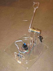
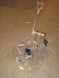
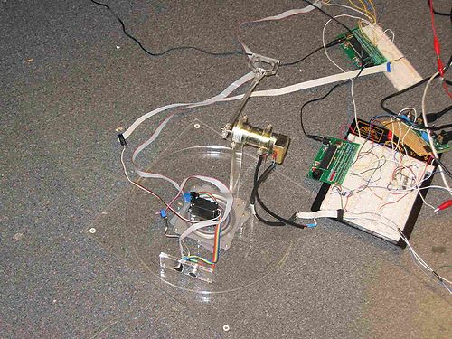
A throwing arm propelled by a Pittman motor is mounted on a turntable and throws the ball into the "hoop." The hoop is wrapped in reflective tape and an IR emitter, receiver pair is used to sense where the IR is reflected most (the hoop with highly reflective tape). An ultrasonic sensor then pings the hoop for the distance of the hoop. With this information, the arm is able to "make a basket." |
A throwing arm propelled by a Pittman DC brush motor is mounted on a turntable and throws the ball into the "hoop." The hoop is wrapped in reflective tape and an IR emitter, receiver pair is used to sense where the IR is reflected most (the hoop with highly reflective tape). An ultrasonic sensor then pings the hoop for the distance of the hoop. With this information, the arm is able to "make a basket." |
||
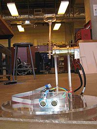
[[Image:Mechatronics2009Bball|Entire system|left|thumb|200px]][[Image:mech2009bballcloseup|Front view|left|thumb|200px]][[Image:mech2009bballcloseupalternate|Close up|left|thumb|350px]] |
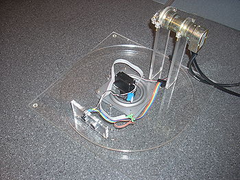
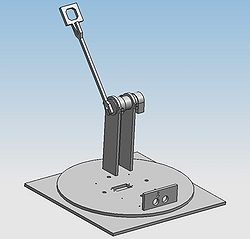
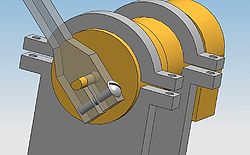
[[Image:Mechatronics2009Bball|Entire system|left|thumb|200px]][[Image:mech2009bballcloseup|Front view|left|thumb|200px]][[Image:mech2009bballcloseupalternate|Close up|left|thumb|350px]] |
||
<br><br><br><br><br><br><br><br><br><br><br><br><br><br><br><br><br><br> |
<br><br><br><br><br><br><br><br><br><br><br><br><br><br><br><br><br><br> |
||
| Line 46: | Line 46: | ||
The Pittman motor, H-Bridge, and encoder chip circuit is more complex. This circuit is run by PIC2. The information collected about the hoop location is communicated from PIC1 to PIC2. The Pittman is used to launch the ball. After the hoop is found, the arm attached to the Pittman launches the ball into the hoop. The shaft rotates forward and then reverses to its previous position. The device is then ready to find the hoop and launch the ball again. |
The Pittman motor, H-Bridge, and encoder chip circuit is more complex. This circuit is run by PIC2. The information collected about the hoop location is communicated from PIC1 to PIC2. The Pittman is used to launch the ball. After the hoop is found, the arm attached to the Pittman launches the ball into the hoop. The shaft rotates forward and then reverses to its previous position. The device is then ready to find the hoop and launch the ball again. |
||
The two |
The two PICs communicated with a common ground and wire connecting RC6 and RC7 as shown in the diagram. The power supply was two 12 volt power supplies connected in series to give a total of 24 volts. |
||
=== Electrical Components === |
=== Electrical Components === |
||
<table border=1> |
<table border=1> |
||
<tr><th>Part</th><th>Part No.</th><th>Qty</th><th>Vendor</th><th>Price (Total)</th></tr> |
<tr><th>Part</th><th>Part No.</th><th>Qty</th><th>Vendor</th><th>Price (Total)</th></tr> |
||
<tr><td>PICs</td><td> |
<tr><td>PICs</td><td>PIC18F4520</td><td>2</td><td>Lab</td><td>-</td></tr> |
||
<tr><td>Encoder</td><td>LS7083</td><td>1</td><td>Lab</td><td>-</td></tr> |
<tr><td>Encoder</td><td>LS7083</td><td>1</td><td>Lab</td><td>-</td></tr> |
||
<tr><td>H-Bridge</td><td>L298N</td><td>1</td><td>Lab</td><td>-</td></tr> |
<tr><td>H-Bridge</td><td>L298N</td><td>1</td><td>Lab</td><td>-</td></tr> |
||
| Line 68: | Line 68: | ||
== Code == |
== Code == |
||
We used two PICs for this project. One ran the motor control since we wanted the smallest interrupt possible for the most accurate speed control. The other PIC ran the servo attached to the turntable as well as the infrared and ultrasonic sensors. |
|||
The motor was controlled using a PD controller which controlled both speed and position. Theory behind the controller was that if accurate speed control could be achieved along with the ability to control the release point by stopping the motor, we could control the distance the ball traveled to a high degree of accuracy having it follow simple kinematic equations. The launch was triggered when the ultrasonic sensor distance was sent to it. We opted against I2C and instead went with RS-232 for simplicity since we were only sending two bytes of data. |
|||
The turntable PIC controlled the RC servo, infrared emitter, infrared phototransistor, and PING ultrasonic ranger. The servo cycled through its full range while recording the maximum value from the phototransistor and its position in the servo cycle, returning to the position of maximum infrared light. The [[Ultrasonic_ranging|PING]] ultrasonic ranger was then used to determine the distance, which was then sent over RS-232 to the motor controlling PIC. |
|||
Full source code of the motor controller can be found [[Media:Motor-Control.c|here]]. <br> |
|||
Full source code of the turntable controller can be found [[Media:Turntable-Control.c|here]] |
|||
== Turntable Control == |
|||
for (maxvalue=0; RCservo0>(1500+4000)/8; RCservo0-=1){ |
|||
delay_us(500); |
|||
} |
|||
for (RCservo0=(1500+4000)/8; RCservo0<(12500-1000)/8; RCservo0+=1 ) { |
|||
value = read_adc(); |
|||
output_d(value>>2); // on port D show only the most significant 8 of the 10 bits; tricky >> means shift right 2 bits |
|||
delay_ms(5); |
|||
if (value>maxvalue) { |
|||
hoopposition=RCservo0; //record position where max ir reflection was detected (the position of the hoop) |
|||
maxvalue=value; |
|||
} |
|||
} |
|||
for (RCservo0=(12500-1000)/8; RCservo0>hoopposition+15; RCservo0-=1 ) { |
|||
delay_us(500); |
|||
} |
|||
RCservo0=hoopposition+15; //move servo to hoop position |
|||
delay_ms(2000); |
|||
avgdistance=0; |
|||
for (counter=0; counter<11; counter+=1) { //distance sensing loop |
|||
output_high(PIN_C5); |
|||
delay_us(5); |
|||
output_low(PIN_C5); |
|||
input(PIN_C5); |
|||
delay_ms(20); //changed from 20 |
|||
avgdistance = avgdistance+distance; |
|||
} |
|||
== PD Controller == |
|||
#INT_TIMER2 // designates that this is the routine to call when timer3 overflows |
|||
void Timer2isr() { |
|||
milsecs++; |
|||
if ((milsecs & 7) == 0) { // servo routine every 4ms is plenty. 250x/sec |
|||
//update counters and encoder |
|||
upCount = get_timer0(); |
|||
encoderActual += upCount - lastUpCount; |
|||
downCount = get_timer1(); |
|||
encoderActual -= downCount - lastDownCount; |
|||
lastUpCount = upCount; |
|||
lastDownCount = downCount; |
|||
We used hardware encoders due to the speed of rotation of the shaft. |
|||
theta = (int16)(encoderActual - offset) % EncCount; |
|||
thetaError = (signed int32)thetaTarget- (signed int32)theta; |
|||
Theta was used for position control. Due to the way we implemented it, the motor was only was only allowed 359.9 degrees of rotation which was suitable for our launching arm. |
|||
//speed controls whether it is in forward or reverse |
|||
if(thetaError > 0) speed = targetSpeed; |
|||
else if(thetaError < 0) speed = -targetSpeed; |
|||
A positive thetaError indicated that the motor needed to move CCW to reach its destination A negative thetaError indicated that the motor needed to move CW to reach its destination. |
|||
encoderTarget += speed; //need to add accuracy to speed |
|||
encoderTargetTheta = (int16)(encoderTarget) % EncCount; |
|||
if(encoderTargetTheta > thetaTarget && speed > 0) { |
|||
encoderTarget -= encoderTargetTheta - thetaTarget; |
|||
targetSpeed = 0; |
|||
} else if(encoderTargetTheta < thetaTarget && speed < 0) { |
|||
encoderTarget += thetaTarget - encoderTargetTheta; |
|||
targetSpeed = 0; |
|||
} |
|||
The encoderTargetTheta was used to handle the case of overshoots and was the theta value of the encoderTarget after the speed was added. If that theta value was above/below (depending on direction) the target theta value, it represented that the input had reached its destination, so the speed drops to zero, and the encoderTarget is set to the correct target value. |
|||
//do calculations for PD controller with new error |
|||
error = encoderTarget - (encoderActual - initialCount); |
|||
derivative = error - lastError; |
|||
lastError = error; |
|||
//At different speeds, need different gains, higher kps and kds for higher speeds ect... |
|||
if(speed <= 5) { |
|||
Torque = 3*error + 2*derivative; |
|||
} else |
|||
if (speed <= 75) { |
|||
Torque = 1.25 * error + 3 * derivative; |
|||
} else if (speed <= 100) { |
|||
Torque = 2 * error + 6 * derivative; |
|||
} else { //speed > 100 |
|||
Torque = pGain * error + dGain * derivative; |
|||
} |
|||
In tuning the PD controller, it was found that different speeds needed different tunings in order to receive a smooth and accurate response. These values represent the best values we were able to obtain in tuning. |
|||
if(error > 0) { //going in the CCW direction, Torque positive |
|||
output_low(PIN_C4); |
|||
} |
|||
else if(error < 0) { |
|||
//invert for PWM |
|||
Torque = 624 + Torque; |
|||
output_high(PIN_C4); |
|||
if(launching == 1 && thetaError < 0) { //used to tune when launching |
|||
launching = 0; |
|||
thetaTarget = 300; |
|||
targetSpeed = 10; |
|||
} |
|||
} |
|||
Set PWM values to make motor go forward or reverse. Also, the case where 'launching==1' is to return the arm to a loading position after the arm has shot a ball. |
|||
if(Torque < 0) Torque = 0; |
|||
if(Torque > 624) Torque = 624; |
|||
set_pwm1_duty(Torque); |
|||
} |
|||
} |
|||
Set the motor's PWM and check for maximum and minimum values. 624 was used instead of 78 for PWM values based on how we set up our timer2. |
|||
== PIC to PIC communication with RS-232 == |
|||
We choose to use RS-232 to communicate between PICs because of the small amount of data we were sending (a single int16) and to avoid the overhead required by I2C. We accomplished this by breaking our values into 8-bit chunks cast as chars and sending them one at a time. |
|||
sendDistance = avgdistance*100; //distance in cm\ |
|||
//Break distance into two 8-bit ints and cast as chars to send over RS-232 |
|||
//Will be reassembled on other pic |
|||
putc((char)(sendDistance>>8)); |
|||
putc((char)(sendDistance & 255)); |
|||
Code to send value. |
|||
#INT_RDA |
|||
void INTRDAisr() { |
|||
if(kbhit()) { |
|||
if(rsCount == 0) c_0 = getc(); |
|||
else if(rsCount == 1) { |
|||
c_1 = getc(); |
|||
distance = (int16)c_1 + ((int16)c_0<<8); |
|||
CalculateAndLaunch((float)distance); |
|||
} |
|||
} |
|||
rsCount++; |
|||
if(rsCount >= 2) rsCount = 0; |
|||
} |
|||
This interrupt is called when the hardware RS-232 receives a byte of data. Once two bytes of data are received (int16), the interrupt reassembles them into a single int16 and calls CalculateAndLaunch(). |
|||
== Distance Calculation == |
|||
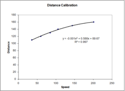
Shot distance was based on a second order polynomial fit we obtained experimentally. The data we collected is shown in the image on the right. [[Image:Distance-Calibration-basketball.png|Calibration data and Trendline|thumb|250px|right]] |
|||
void LaunchBall(int16 speed, int16 angle) { |
|||
targetSpeed = speed; |
|||
thetaTarget = angle; |
|||
launching=1; |
|||
} |
|||
void CalculateAndLaunch(float dist) { |
|||
dist = dist+30; //adjust for distance between ranger and motor |
|||
shotSpeed = -0.0012*(dist*dist) + 0.5884*dist + 89.678; |
|||
LaunchBall((int16)(shotSpeed/2), 3000); |
|||
} |
|||
== Results == |
== Results == |
||
In the end, the project ultimately succeeded -- baskets could be made. However, better tuning for the motor control and needs to be developed for more consistent results. |
In the end, the project ultimately succeeded -- baskets could be made. However, better tuning for the motor control and needs to be developed for more consistent results. |
||
[http://www.youtube.com/watch?v=Y466dzP-qiY Link To Video] |
|||
LINK TO VIDEO HERE |
|||
===Problems Encountered=== |
===Problems Encountered=== |
||
*Attempting to integrate multiple pics and circuits onto one circuit board did not give good results. Ultimately, we had to use separate boards for each pic. |
*Attempting to integrate multiple pics and circuits onto one circuit board did not give good results. Ultimately, we had to use separate boards for each pic. This could be due to the effect of motor noise on our control circuitry. |
||
*Motor control was an intense programming effort -- almost a project in its own right. Trying to combine the motor control and |
*Motor control was an intense programming effort -- almost a project in its own right. Trying to combine the motor control and calibrate our throwing distance was difficult. Designing a functioning throwing device along with getting the rest of the project implemented was difficult to complete with the given time constraints. |
||
*Many components burned out. Encoder chips also burned out. The PING sensor burned out as well. We are not sure of the cause. |
*Many components burned out. Fly back diodes were implemented however, we still went through quite a few H-bridges. Encoder chips also burned out. The PING sensor burned out as well. We are not sure of the cause of some of these part failures. |
||
*The length of wires for the Encoder A and B should be limited. |
*The length of wires for the Encoder A and B should be limited. When using long wires running from the encoder, we were not able to get our encoder chip to function properly. Replacing them with shorter wires fixed the issue. Because the signal from the encoder is switching at such high speeds, the loss in the long wires played a significant effect resulting in a faulty encoder count. Larger diameter wires may be an alternate solution to this problem. |
||
== Notes == |
== Notes == |
||
A few things we might change if we did it again: |
A few things we might change if we did it again: |
||
*Simplify the motor control portion of the project. Trying to implement a speed control using the encoder count was difficult to implement. Simply using PWM to drive the motor at different speeds may have been sufficient. |
|||
*Try another actuator that requires less intense motor control. |
|||
*Test different wires for length and diameter for optimal performance for the Encoder A and B connections |
*Test different wires for length and diameter for optimal performance for the Encoder A and B connections. |
||
*Combine the PICs on one circuit board, solving the issues we encountered when attempting this. |
|||
*Figure out why the PICs could not be combined onto a single board. |
|||
*Perform a more detailed calibration, adjusting starting position, final launching position, and speed to get improved control over throwing distance. |
|||
*Introduce feedback control once the motor is tuned. Sense the distance the ball travels and adjust accordingly if the shot misses. |
|||
Latest revision as of 02:51, 20 March 2009
<br=clear all>
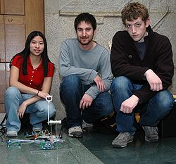
Team Members
- John Rula (Mechanical Engineering, Class of 2009)
- Alex Wojcicki (Mechanical Engineering, Class of 2009)
- Meredith Chow (Electrical Engineering, Class of 2010)
Introduction
A throwing arm propelled by a Pittman DC brush motor is mounted on a turntable and throws the ball into the "hoop." The hoop is wrapped in reflective tape and an IR emitter, receiver pair is used to sense where the IR is reflected most (the hoop with highly reflective tape). An ultrasonic sensor then pings the hoop for the distance of the hoop. With this information, the arm is able to "make a basket."
Mechanical Design
The major mechanical components were machined out of clear acrylic using the laser cutter in the machine shop. Holes were machined and threaded as required. The base is a square (12" x 12") with threaded holes for attachment to the purchased turntable bearing. The turntable has threaded holes for attachment to the turntable bearing as well. Large holes were added to the turntable for screw access during assembly because once one of the parts is attached to the turntable, the screws would otherwise not be able to be tightened. The turntable features a rectangular cutout for the servo motor and threaded holes for mounting. There are additional through holes for mounting the sensor bracket and the motor supports.
Two motor supports were designed to accept the Pittman motor and hold it six inches above the turntable surface. Fasteners are inserted from below the turntable into threaded holes in the motor supports. Clamps were designed to thread onto the supports and secure the motor in place. The sensors (IR emitter/receiver pair and ultrasonic sensor) are mounted on a machined acrylic bracket that which is attached to the turntable again through fasteners inserted underneath the turntable.
The arm is also made of laser cut acrylic. It was designed with a close fit on the flat of the motor shaft and with a clamp for tightening using a threaded fastener. For manufacturing reasons, the ball holding portion of the arm was cut out of a separate piece of acrylic and secured to the end of the throwing arm.
The hoop can be anything with the highly reflective tape around it. It is suggested to have a circular profile for better performance detecting its center using the IR emitter/receiver.
Mechanical Components
| Part | Part No. | Qty | Vendor | Price (Total) |
|---|---|---|---|---|
| Pittman Motor | GM8712 | 1 | Lab | - |
| RC Servo Motor - Futaba | S3004 | 1 | Lab | - |
| Acrylic .25" Thick, 24"X 24" | 8560K357 | 1 | McMaster | $39.63 |
| Corrosion-Resistant Turntable | 6031K17 | 1 | McMaster | $2.42 |
| Fasteners | - | 24 | Shop supply | - |
| Rubber Feet | - | 4 | Lab | - |
Electrical Design
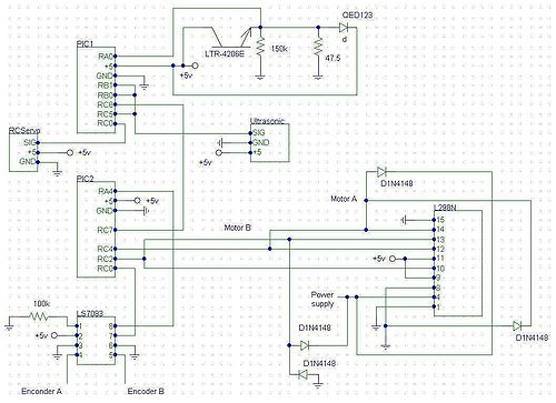
The IR pair, ultrasonic, and servo have a relatively simple circuit. In the diagram below, the IR pair, ultrasonic, and servo are controlled by the program on PIC1. The IR pair and ultrasonic sensor are stacked vertically and inserted into the fitted holes on the laser cut acrylic. Because of the close proximity of the IR pair, to prevent saturation of the IR receiver, the emitter was wrapped in electrical tape. This allowed for the detection of reflected IR rather than from the emitter right below the detector. The RC servo goes through a sweep looking for the hoop. It finds the hoop by storing the location of the highest IR detection. The reflective tape used in Design Challenge 2008 and 2009 was used to wrap the hoop and is used to assist in the finding of the hoop as it reflects more IR radiation than most common objects. After making its sweep, the servo returns to the position where the most IR was detected. The ultrasonic sensor will then ping the hoop to find the distance of the hoop.
The Pittman motor, H-Bridge, and encoder chip circuit is more complex. This circuit is run by PIC2. The information collected about the hoop location is communicated from PIC1 to PIC2. The Pittman is used to launch the ball. After the hoop is found, the arm attached to the Pittman launches the ball into the hoop. The shaft rotates forward and then reverses to its previous position. The device is then ready to find the hoop and launch the ball again.
The two PICs communicated with a common ground and wire connecting RC6 and RC7 as shown in the diagram. The power supply was two 12 volt power supplies connected in series to give a total of 24 volts.
Electrical Components
| Part | Part No. | Qty | Vendor | Price (Total) |
|---|---|---|---|---|
| PICs | PIC18F4520 | 2 | Lab | - |
| Encoder | LS7083 | 1 | Lab | - |
| H-Bridge | L298N | 1 | Lab | - |
| Ping Ultrasonic Sensor | 28015 | 1 | Lab 5 supply | - |
| IR Emitter | QED123 | 1 | Lab | - |
| IR Phototransistor | LTR-4206E | 1 | Lab | - |
| Diodes | 1N4148 | 4 | Lab | - |
| Resistors | 47.5/150K | 2 | Lab | - |
Circuit Diagram
Code
We used two PICs for this project. One ran the motor control since we wanted the smallest interrupt possible for the most accurate speed control. The other PIC ran the servo attached to the turntable as well as the infrared and ultrasonic sensors.
The motor was controlled using a PD controller which controlled both speed and position. Theory behind the controller was that if accurate speed control could be achieved along with the ability to control the release point by stopping the motor, we could control the distance the ball traveled to a high degree of accuracy having it follow simple kinematic equations. The launch was triggered when the ultrasonic sensor distance was sent to it. We opted against I2C and instead went with RS-232 for simplicity since we were only sending two bytes of data.
The turntable PIC controlled the RC servo, infrared emitter, infrared phototransistor, and PING ultrasonic ranger. The servo cycled through its full range while recording the maximum value from the phototransistor and its position in the servo cycle, returning to the position of maximum infrared light. The PING ultrasonic ranger was then used to determine the distance, which was then sent over RS-232 to the motor controlling PIC.
Full source code of the motor controller can be found here.
Full source code of the turntable controller can be found here
Turntable Control
for (maxvalue=0; RCservo0>(1500+4000)/8; RCservo0-=1){
    delay_us(500);
}

for (RCservo0=(1500+4000)/8;  RCservo0<(12500-1000)/8; RCservo0+=1  ) {
   value = read_adc();
   output_d(value>>2);     // on port D show only the most significant 8 of the 10 bits; tricky >> means shift right 2 bits
   delay_ms(5);
   if (value>maxvalue) {
      hoopposition=RCservo0;              //record position where max ir reflection was detected (the position of the hoop)
      maxvalue=value;
   }
}


 for (RCservo0=(12500-1000)/8; RCservo0>hoopposition+15; RCservo0-=1 ) {
   delay_us(500);
 }

 RCservo0=hoopposition+15;                         //move servo to hoop position
 delay_ms(2000);
 avgdistance=0;

 for (counter=0; counter<11; counter+=1) {            //distance sensing loop
   output_high(PIN_C5);
   delay_us(5);
   output_low(PIN_C5);
   input(PIN_C5);
   delay_ms(20); //changed from 20
   avgdistance = avgdistance+distance;
 }
PD Controller
#INT_TIMER2       // designates that this is the routine to call when timer3 overflows
void Timer2isr() {
  milsecs++;
  if ((milsecs & 7) == 0) {      // servo routine every 4ms is plenty.  250x/sec
    //update counters and encoder
    upCount = get_timer0();
    encoderActual += upCount - lastUpCount;
    downCount = get_timer1();
    encoderActual -= downCount - lastDownCount;
    lastUpCount = upCount;
    lastDownCount = downCount;
We used hardware encoders due to the speed of rotation of the shaft.
    theta = (int16)(encoderActual - offset) % EncCount;
    thetaError = (signed int32)thetaTarget- (signed int32)theta;
Theta was used for position control. Due to the way we implemented it, the motor was only was only allowed 359.9 degrees of rotation which was suitable for our launching arm.
    //speed controls whether it is in forward or reverse
    if(thetaError > 0) speed = targetSpeed;
    else if(thetaError < 0) speed = -targetSpeed;
A positive thetaError indicated that the motor needed to move CCW to reach its destination A negative thetaError indicated that the motor needed to move CW to reach its destination.
    encoderTarget += speed; //need to add accuracy to speed
    encoderTargetTheta = (int16)(encoderTarget) % EncCount;

    if(encoderTargetTheta > thetaTarget && speed > 0) {
       encoderTarget -= encoderTargetTheta - thetaTarget;
       targetSpeed = 0;
    } else if(encoderTargetTheta < thetaTarget && speed < 0) {
       encoderTarget += thetaTarget - encoderTargetTheta;
       targetSpeed = 0;
    }
The encoderTargetTheta was used to handle the case of overshoots and was the theta value of the encoderTarget after the speed was added. If that theta value was above/below (depending on direction) the target theta value, it represented that the input had reached its destination, so the speed drops to zero, and the encoderTarget is set to the correct target value.
    //do calculations for PD controller with new error
    error = encoderTarget - (encoderActual - initialCount);
    derivative = error - lastError;
    lastError = error;

    //At different speeds, need different gains, higher kps and kds for higher speeds ect...
    if(speed <= 5) {
        Torque = 3*error + 2*derivative;
    } else
    if (speed <= 75) {
        Torque = 1.25 * error + 3 * derivative;
    } else if (speed <= 100) {
        Torque = 2 * error + 6 * derivative;
    } else {  //speed > 100
        Torque = pGain * error + dGain * derivative;
    }
In tuning the PD controller, it was found that different speeds needed different tunings in order to receive a smooth and accurate response. These values represent the best values we were able to obtain in tuning.
    if(error > 0) {   //going in the CCW direction, Torque positive
        output_low(PIN_C4);
    }
    else if(error < 0) {
        //invert for PWM
        Torque = 624 + Torque;
        output_high(PIN_C4);
        if(launching == 1 && thetaError < 0) { //used to tune when launching
            launching = 0;
            thetaTarget = 300;
            targetSpeed = 10;
        }
    }
Set PWM values to make motor go forward or reverse. Also, the case where 'launching==1' is to return the arm to a loading position after the arm has shot a ball.
    if(Torque < 0) Torque = 0;
    if(Torque > 624) Torque = 624;
    set_pwm1_duty(Torque);

  }
}
Set the motor's PWM and check for maximum and minimum values. 624 was used instead of 78 for PWM values based on how we set up our timer2.
PIC to PIC communication with RS-232
We choose to use RS-232 to communicate between PICs because of the small amount of data we were sending (a single int16) and to avoid the overhead required by I2C. We accomplished this by breaking our values into 8-bit chunks cast as chars and sending them one at a time.
sendDistance = avgdistance*100; //distance in cm\

//Break distance into two 8-bit ints and cast as chars to send over RS-232
//Will be reassembled on other pic
putc((char)(sendDistance>>8));
putc((char)(sendDistance & 255));
Code to send value.
#INT_RDA
void INTRDAisr() {

   if(kbhit()) {
      if(rsCount == 0) c_0 = getc();
      else if(rsCount == 1) {
         c_1 = getc();
         distance = (int16)c_1 + ((int16)c_0<<8);
         CalculateAndLaunch((float)distance);
      }
   }

   rsCount++;
   if(rsCount >= 2) rsCount = 0;
}
This interrupt is called when the hardware RS-232 receives a byte of data. Once two bytes of data are received (int16), the interrupt reassembles them into a single int16 and calls CalculateAndLaunch().
Distance Calculation
Shot distance was based on a second order polynomial fit we obtained experimentally. The data we collected is shown in the image on the right.
void LaunchBall(int16 speed, int16 angle) {
   targetSpeed = speed;
   thetaTarget = angle;
   launching=1;
}

void CalculateAndLaunch(float dist) {
   dist = dist+30; //adjust for distance between ranger and motor
   shotSpeed = -0.0012*(dist*dist) + 0.5884*dist + 89.678;
   LaunchBall((int16)(shotSpeed/2), 3000);
}
Results
In the end, the project ultimately succeeded -- baskets could be made. However, better tuning for the motor control and needs to be developed for more consistent results.
Problems Encountered
- Attempting to integrate multiple pics and circuits onto one circuit board did not give good results. Ultimately, we had to use separate boards for each pic. This could be due to the effect of motor noise on our control circuitry.
- Motor control was an intense programming effort -- almost a project in its own right. Trying to combine the motor control and calibrate our throwing distance was difficult. Designing a functioning throwing device along with getting the rest of the project implemented was difficult to complete with the given time constraints.
- Many components burned out. Fly back diodes were implemented however, we still went through quite a few H-bridges. Encoder chips also burned out. The PING sensor burned out as well. We are not sure of the cause of some of these part failures.
- The length of wires for the Encoder A and B should be limited. When using long wires running from the encoder, we were not able to get our encoder chip to function properly. Replacing them with shorter wires fixed the issue. Because the signal from the encoder is switching at such high speeds, the loss in the long wires played a significant effect resulting in a faulty encoder count. Larger diameter wires may be an alternate solution to this problem.
Notes
A few things we might change if we did it again:
- Simplify the motor control portion of the project. Trying to implement a speed control using the encoder count was difficult to implement. Simply using PWM to drive the motor at different speeds may have been sufficient.
- Test different wires for length and diameter for optimal performance for the Encoder A and B connections.
- Combine the PICs on one circuit board, solving the issues we encountered when attempting this.
- Perform a more detailed calibration, adjusting starting position, final launching position, and speed to get improved control over throwing distance.
