Difference between revisions of "Automated Fish Refuge"
James Cooper (talk | contribs) |
James Cooper (talk | contribs) |
||
| (15 intermediate revisions by the same user not shown) | |||
| Line 50: | Line 50: | ||
== How To Adjust Setup == |
== How To Adjust Setup == |
||
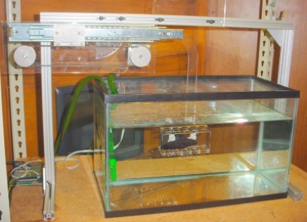
We designed this project to easily configure to the changing needs of the user. On the mechanical side, the base is made from 80/20 aluminum square (1"x1") framing that has easily adjustable connections with just an allen wrench. This allows the user to raise or lower the height of the arm and also adjust the outside legs to the length of the tank. The sliding quarter circles allow the user to adjust the location and angle of the arm (and the oscillating motion) |
We designed this project to easily configure to the changing needs of the user. On the mechanical side, the base is made from 80/20 aluminum square (1"x1") framing that has easily adjustable connections with just an allen wrench. This framing system allows the user to raise or lower the height of the arm and also adjust the outside legs to the length of the tank. The sliding quarter circles allow the user to adjust the location and angle of the arm (and the oscillating motion) in 10 degree increments. The arm attaches to the quarter circle by two long bolts and wing nuts that keep them in place. Similarly, the end of the arm has another quarter circle which allows for the fish enclosure to independently adjust to any angle and has similar plastic bolts and plastic wing nuts. |
||
The design of the program also allows for a variety of configurations for specific needs. The PIC's programming acts as simply a transfer from an array of delay times to a signal for the L297 chip. The conversion from user input to an array of delay times is done in |
The design of the program also allows for a variety of configurations for specific needs. The PIC's programming acts as simply a transfer from an array of delay times to a signal for the L297 chip. The conversion from user input to an array of delay times is done in MATLAB, which is an easily configured program. As noted below, there are two main types of programs that run the device: the functions that convert user input to delay times array function and the function that sends the array to the PIC. This modularity adds another dimension of adjustability where the user can put in any function or even create their own simple MATLAB function to send a specific array to the second program. |
||
== How To Control == |
== How To Control == |
||
Once you have the setup |
Once you have the setup oriented in the desired starting position, all you need to do to make the refuge move is send the PIC the control commands from MATLAB. In this section, we will go over how to create the array that contains the control parameters, and then how to send it over to the PIC. We separated this into two function calls to allow the user to have complete control over the path selection, and then allow the sending function to check to make sure the path selected is valid. |
||
===Generating The Path=== |
===Generating The Path=== |
||
The user has 5 different |
The user has 5 different ways to generate the path. We created a MATLAB function to generate a square wave, a triangle wave, and a sine wave. We also created a function that allows the user to put in a function handle, and then get out a path. The final option is for the user to create their own without the assistance of any of the functions we created. |
||
The path is an array of delay times between steps for the stepper motor. The way the stepper motor |
The path is an array of delay times between steps for the stepper motor. The way the stepper motor works is you send a pulse to the motor every time you want it to take a step. Each step on the stepper motor is a 1.8 degrees rotation of the shaft. The outer diameter of the pulley attached to the shaft of the motor is 45.2882 mm, which means the distance per step is 0.7114 mm. The array of delay times is the amount of time in between each step in microseconds (10^-6 seconds). The sign of the delay time states which direction it is going in: positive for forward, and negative for backward. |
||
<br> |
<br> |
||
====Square Wave==== |
====Square Wave==== |
||
| Line 79: | Line 79: | ||
====Sine Wave==== |
====Sine Wave==== |
||
For the [[media:sin_to_delay.m|sine wave generator]], all you need to do is enter the magnitude of travel (mm), and the frequency (rad/s). The sine wave generator will first have the refuge go forward, before it goes backward. The sine wave generator takes some time to generate the array of delay times, since it uses the function handle converter function to create the |
For the [[media:sin_to_delay.m|sine wave generator]], all you need to do is enter the magnitude of travel (mm), and the frequency (rad/s). The sine wave generator will first have the refuge go forward, before it goes backward. The sine wave generator takes some time to generate the array of delay times, since it uses the function handle converter function to create the sine wave function, as will be discussed. |
||
[time_array]=sin_to_delay(mag,wn) |
[time_array]=sin_to_delay(mag,wn) |
||
%time_array is the outputted array of delay times (us) |
%time_array is the outputted array of delay times (us) |
||
| Line 86: | Line 86: | ||
====Function Handle==== |
====Function Handle==== |
||
For the [[media:fun_to_delay.m|function handle converter]], all you need to do is enter a function handle of the displacement profile you would like to follow. This function works by checking every millisecond to |
For the [[media:fun_to_delay.m|function handle converter]], all you need to do is enter a function handle of the displacement profile you would like to follow. This function works by checking every millisecond to see if the step distance has occurred, and then taking that time difference and setting it to the list of the delay times. Then it sets that delay time as positive or negative depending on whether the displacement is positive or negative. This process repeats until the the net displacement goes back to 0. If this never happens, then the function will run forever. The displacement at time = 0 is considered the starting position (current displacement = 0), and the value the function handle puts out does not have to be 0. The function displays the current displacement as it runs. |
||
[time_array]=fun_to_delay(fun) |
[time_array]=fun_to_delay(fun) |
||
%time_array is the outputted array of delay times (us) |
%time_array is the outputted array of delay times (us) |
||
| Line 92: | Line 92: | ||
====Create Your Own==== |
====Create Your Own==== |
||
The last option to create the array of delay times is to |
The last option to create the array of delay times is to make it yourself. With this method, you can create the array any way you want to. Be sure to input the time in microseconds it takes to travel 0.7114 mm. Also, you need to input a sign (+/-) for your delay time depending on which direction you want to go. When creating the array of delay times, make sure to have an equal number of positive and negative ones, since if you don't, the communication function will not send your array, because your path will not go equal distances in both directions. |
||
===Sending Path=== |
===Sending Path=== |
||
For the [[media:serial_com.m|serial communication ]] function, all you need to do is input the array of delay times, com port, number of cycles, and how you would like it to handle step times that are too large and too small. Com port should be inputted as a string of the location where |
For the [[media:serial_com.m|serial communication ]] function, all you need to do is input the array of delay times, com port, number of cycles, and how you would like it to handle step times that are too large and too small. Com port should be inputted as a string of the location where your RS232 cable is plugged into your computer. If you don't know what that is, try using 'COM4' at first, and then if this is incorrect, you will get an error message telling you which com ports are open so you know what to try next. Cycles is the number of times you want the program to run though your array of delay times. Too fast and too slow inputs tell the program how you want it to handle delay times that are either too fast or too slow. The too fast value in the program is for values that are too fast for the setup in ideal conditions, and your setup might need values slower then this value. The too slow value is determined by the largest delay time the PIC can handle (2^16-1), since the delay times are held in variables that 16 bit integers. Input 0 if you want the program to stop if a delay time is out of range. Input 1 if you want the program to correct that improper delay time with the maximum or minimum possible value. |
||
serial_com(time_array,com_port,cycles,too_fast,too_slow) |
serial_com(time_array,com_port,cycles,too_fast,too_slow) |
||
%time_array is the inputted array of delay times (us) |
%time_array is the inputted array of delay times (us) |
||
| Line 102: | Line 102: | ||
%too_fast is how you want the program to handle velocities that are too fast |
%too_fast is how you want the program to handle velocities that are too fast |
||
%too_slow is how you want the program to handle velocities that are too slow |
%too_slow is how you want the program to handle velocities that are too slow |
||
The serial communication function checks to make sure inputted delay times are within acceptable velocities, makes sure array of delay time is proper length (can be up to 500 numbers long), and makes sure the inputted path goes the same distance in both directions. If you stop the function after it starts transmitting to the PIC, but before it closes the transmission, then |
The serial communication function checks to make sure inputted delay times are within acceptable velocities, makes sure array of delay time is the proper length (can be up to 500 numbers long), and makes sure the inputted path goes the same distance in both directions. If you stop the function after it starts transmitting to the PIC, but before it closes the transmission, then you should restart MATLAB to clear communication bugs. In that event, you should also click the reset button on the PIC. After plugging in and before transmission, it is recommended that you restart the PIC so you know it is at the proper place in its program to accept the arrays that will be transmitted to it. |
||
<br> |
<br> |
||
The system limits are set at the beginning of the program in case the user would like to change them based on experience with the setup. |
The system limits are set at the beginning of the program in case the user would like to change them based on experience with the setup. |
||
| Line 110: | Line 110: | ||
max_num_cycles=2^16-1; %determined by max variable length for delay time in PIC |
max_num_cycles=2^16-1; %determined by max variable length for delay time in PIC |
||
max_array_length=500; %determined by max array length for delay times in PIC |
max_array_length=500; %determined by max array length for delay times in PIC |
||
pause_time=0.01; % |
pause_time=0.01; %lengths of pauses in transmission |
||
We set the minimum delay time to be 3000 since that is in the range of the largest delay times where the motor had skipping issues. This does not guarantee that delay times larger then 3000 will not skip, but it makes sure you know to expect skipping if the delay time is less. This number is the total delay time in the PIC minus 1000, since internally in the PIC there is a 1000 microsecond delay time for the signal.<br> |
We set the minimum delay time to be 3000 since that is in the range of the largest delay times where the motor had skipping issues. This does not guarantee that delay times larger then 3000 will not skip, but it makes sure you know to expect skipping if the delay time is less. This number is the total delay time in the PIC minus 1000, since internally in the PIC there is a 1000 microsecond delay time for the signal.<br> |
||
We set maximum delay time to 2^16-1 since the delay times are being sent to the PIC are being held in 16 bit integers, which means this is the largest number it can hold.<br> |
We set maximum delay time to 2^16-1 since the delay times are being sent to the PIC are being held in 16 bit integers, which means this is the largest number it can hold.<br> |
||
We set maximum number of cycles to 2^16-1 since the number of cycles is being sent to the PIC to be held in a 16 bit integer, which means this is the largest number it can hold.<br> |
We set maximum number of cycles to 2^16-1 since the number of cycles is being sent to the PIC to be held in a 16 bit integer, which means this is the largest number it can hold.<br> |
||
We set the maximum array length to be 500 since that is the length of the |
We set the maximum array length to be 500 since that is the length of the arrays in the PIC, and that fills up the PIC's memory.<br> |
||
The pause time is set to 0.01 seconds since that was experimentally determined to be a reliable time in between sending data to the PIC. |
The pause time is set to 0.01 seconds since that was experimentally determined to be a reliable time in between sending data to the PIC. |
||
| Line 121: | Line 121: | ||
<br> |
<br> |
||
=== Reading Information === |
=== Reading Information === |
||
We read in using RS 232 serial communication at a baud rate of 19200. We send everything digit by digit to protect the information because we |
We read in using RS 232 serial communication at a baud rate of 19200. We send everything digit by digit to protect the information because we heard there have been some issues previously using RS232 with some high byte numbers before. |
||
<br> |
<br> |
||
First, read in length of arrays to be transmitted. |
First, read in length of arrays to be transmitted. |
||
| Line 171: | Line 171: | ||
== Electrical Design == |
== Electrical Design == |
||
The circuit design and building is minimal for this project. The only necessary circuitry is to connect the unipolar stepper motor with the |
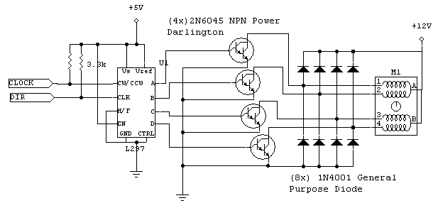
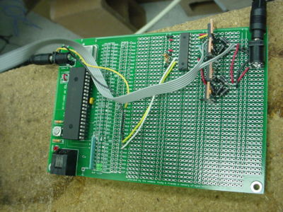
The circuit design and building is minimal for this project. The only necessary circuitry is to connect the unipolar stepper motor with the PIC, and connect the RS232 cable to the PIC. Please see the pages for the [[Unipolar_Stepper_Motor_Driver_Circuit|Unipolar Stepper Motor Driver Circuit]] and the [[PIC_RS232|PIC RS232]] cable for more information on how they work and how to set them up. |
||
<br> |
<br> |
||
[[image:unipolar stepper circuit schematic.png|center]] |
[[image:unipolar stepper circuit schematic.png|center]] |
||
| Line 206: | Line 206: | ||
== Mechanical Design == |
== Mechanical Design == |
||
[[image:fish_setup.bmp|thumb|right|250px|Setup]] |
[[image:fish_setup.bmp|thumb|right|250px|Setup]] |
||
The main philosophy for the mechanical design is to build something |
The main philosophy for the mechanical design is to build something reliable and adjustable. For the frame, we used Aluminum Fractional T-Slotted Framing System in order to make it strong and adjustable. The 1" by 1" beams are overkill for the loads that will be applied, and the weight of the frame will make sure it does not move. Using the T-Slotted Framing System allows for easy adjustment of the dimension of the frame, since all you have to do is undo a bolt in order to slide the connecting pieces to your location of choice. This allows one to easily change the size of the frame if one were to get a new fish tank. Also, it allows easy movement of the quarter circle that holds the arm up. The quarter circles allow you to adjust the angle of the arm and box in 10 degree increments by the adjustment of bolts with wing nuts. This allows great flexibility in the angles of the setup. All this is to make a system that is solid and will only move along the desired axis. The arm, box, quarter circle, and back plane for the motor are made out of 1/4" acrylic because it is a durable plastic material that will not effect the electric field emitted by the fish. |
||
<br><br> |
<br><br> |
||
We used the laser in the shop to cut out the parts made |
We used the laser in the shop to cut out the parts made of acrylic. Here are the CAD files for these parts in case you would like to edit or remake them:<br> |
||
[[media:fish_arm.prt|arm.prt]]<br> |
[[media:fish_arm.prt|arm.prt]]<br> |
||
[[media:fish_box.prt|box.prt]]<br> |
[[media:fish_box.prt|box.prt]]<br> |
||
| Line 219: | Line 219: | ||
[http://www.youtube.com/watch?v=wGOKujMhN88 Video of Automated Fish Refuge] |
[http://www.youtube.com/watch?v=wGOKujMhN88 Video of Automated Fish Refuge] |
||
<br> |
<br> |
||
The MATLAB program successfully converted user input into the delay times array and transferred this array to the PIC. We provided standard wave generators and give the user the ability to create |
The MATLAB program successfully converted user input into the delay times array and transferred this array to the PIC. We provided standard wave generators and give the user the ability to create any kind of motion desired. The transmission process can take up to a minute or two for long distances, but it works reliably. The PIC correctly read the array from the PC and converted it into motor control for the L297 chip. The motor performed well on a horizontal plane, but struggled at faster speeds. It also can struggle as the speed is increased while the arm is brought more vertical due to the added force of gravity. We chose the strongest unipolar stepper motor of our facilities, but this problem should be solved with a stronger motor. In either direction, the water resistance did not seem to have a noticeable affect on the motor. |
||
=== Suggested Improvement === |
=== Suggested Improvement === |
||
The main improvement we would suggest |
The main improvement we would suggest is to get a larger motor to allow faster movement and to improve vertical motion. Other than this the system responded accurately and reliably. |
||
== Further Reading == |
== Further Reading == |
||
[http://en.wikipedia.org/wiki/Apteronotidae Ghost Knifefish |
[http://en.wikipedia.org/wiki/Apteronotidae Ghost Knifefish Wikipedia Entry] |
||
<br> |
<br> |
||
Latest revision as of 19:58, 18 March 2009
Team Members
James Cooper - Junior in Mechanical Engineering
Chris Ryan - Masters Student in Biomedical Engineering
Overview
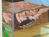
The weakly electric knifefish prefers to hide in tight spaces rather than to swim in the open. The fish will attempt to stay within an enclosure if the enclosure is moved. This provides a unique opportunity to study its behavior and the control of its unique ribbon fin locomotion. The goal of this project was to build a device that moves a box under computer control for Professor MacIver's lab. During operation, the box can oscillate back and forth in one degree of freedom. Unlike most fish, the ribbon fin allows the knifefish to move forward, backward, up, and down. Our device is manually adjustable (for reliability) so that the angle of oscillation and the angle of the enclosure can be set independently, each by steps of 10 degrees. Check out a video!
Parts List
Base
- 8 Feet of 1"x1" Aluminum Fractional T-Slotted Framing System (Order at McMaster.com =$28.04)
- 2 Corner Connectors (Order at McMaster.com = $9.04 each)
- 2 Tee Connectors (Order at McMaster.com = $9.93 each)
- 22 T-Nuts with Cap Screw (Order at McMaster.com = $19.10 for two packs of 15)
Arm
- 1/4 inch Acrylic
- 1 Unipolar Stepper Motor
- 1 Belt Part#:6484K237(Order at McMaster.com = $6.01)
- 2 Pulleys Part#:6495K723 (Order at McMaster.com = $21.14 each)
- 12" Drawer Slider
- 4"x6" Sheet Metal
- 3 Plastic Zip Ties
- 2 Plastic 1/4" bolts and Wing Nuts
- 2 Metal #8 Wing Nuts
- 8 Metal #8 Bolts, Washers, and Nuts
- 4 Metal #8 Spring Washers
- 1 Metal 1/4" Bolt, Washer, and Stop Nut
Circuit
- Unipolar Stepper Motor Driver Circuit
- PIC RS232 Cord
- 5 Volt Power Cord
- 12 Volts 3 Amp Power Supply
How To Adjust Setup
We designed this project to easily configure to the changing needs of the user. On the mechanical side, the base is made from 80/20 aluminum square (1"x1") framing that has easily adjustable connections with just an allen wrench. This framing system allows the user to raise or lower the height of the arm and also adjust the outside legs to the length of the tank. The sliding quarter circles allow the user to adjust the location and angle of the arm (and the oscillating motion) in 10 degree increments. The arm attaches to the quarter circle by two long bolts and wing nuts that keep them in place. Similarly, the end of the arm has another quarter circle which allows for the fish enclosure to independently adjust to any angle and has similar plastic bolts and plastic wing nuts.
The design of the program also allows for a variety of configurations for specific needs. The PIC's programming acts as simply a transfer from an array of delay times to a signal for the L297 chip. The conversion from user input to an array of delay times is done in MATLAB, which is an easily configured program. As noted below, there are two main types of programs that run the device: the functions that convert user input to delay times array function and the function that sends the array to the PIC. This modularity adds another dimension of adjustability where the user can put in any function or even create their own simple MATLAB function to send a specific array to the second program.
How To Control
Once you have the setup oriented in the desired starting position, all you need to do to make the refuge move is send the PIC the control commands from MATLAB. In this section, we will go over how to create the array that contains the control parameters, and then how to send it over to the PIC. We separated this into two function calls to allow the user to have complete control over the path selection, and then allow the sending function to check to make sure the path selected is valid.
Generating The Path
The user has 5 different ways to generate the path. We created a MATLAB function to generate a square wave, a triangle wave, and a sine wave. We also created a function that allows the user to put in a function handle, and then get out a path. The final option is for the user to create their own without the assistance of any of the functions we created.
The path is an array of delay times between steps for the stepper motor. The way the stepper motor works is you send a pulse to the motor every time you want it to take a step. Each step on the stepper motor is a 1.8 degrees rotation of the shaft. The outer diameter of the pulley attached to the shaft of the motor is 45.2882 mm, which means the distance per step is 0.7114 mm. The array of delay times is the amount of time in between each step in microseconds (10^-6 seconds). The sign of the delay time states which direction it is going in: positive for forward, and negative for backward.
Square Wave
For the square wave generator, all you need to do is enter the forward velocity (mm/s), the backward velocity (mm/s), and how far it travels (mm). The square wave generator will first have the refuge go forward, before it goes backward.
   [time_array]=square_to_delay(vel1,vel2,length)
   %time_array is the outputted array of delay times (us)
   %vel1 is forward velocity (mm/s)
   %vel2 is backward velocity (mm/s)
   %length is length traveled (mm)
Triangle Wave
For the triangle wave generator, all you need to do is enter the peak forward velocity (mm/s), the peak backward velocity (mm/s), and how far it travels (mm). The triangle wave generator will first have the refuge go forward, before it goes backward.
   [time_array]=triangle_to_delay(vmax1,vmax2,length)
   %time_array is the outputted array of delay times (us)
   %vmax1 is forward peak velocity (mm/s)
   %vmax2 is backward peak velocity (mm/s)
   %length is length traveled (mm)
Sine Wave
For the sine wave generator, all you need to do is enter the magnitude of travel (mm), and the frequency (rad/s). The sine wave generator will first have the refuge go forward, before it goes backward. The sine wave generator takes some time to generate the array of delay times, since it uses the function handle converter function to create the sine wave function, as will be discussed.
   [time_array]=sin_to_delay(mag,wn)
   %time_array is the outputted array of delay times (us)
   %mag is magnitude of distance traveled (mm)
   %wn is frequency (rad/s)
Function Handle
For the function handle converter, all you need to do is enter a function handle of the displacement profile you would like to follow. This function works by checking every millisecond to see if the step distance has occurred, and then taking that time difference and setting it to the list of the delay times. Then it sets that delay time as positive or negative depending on whether the displacement is positive or negative. This process repeats until the the net displacement goes back to 0. If this never happens, then the function will run forever. The displacement at time = 0 is considered the starting position (current displacement = 0), and the value the function handle puts out does not have to be 0. The function displays the current displacement as it runs.
   [time_array]=fun_to_delay(fun)
   %time_array is the outputted array of delay times (us)
   %fun is function handle of displacement as a function of time.  Displacement should be in mm, and time should be in seconds.
Create Your Own
The last option to create the array of delay times is to make it yourself. With this method, you can create the array any way you want to. Be sure to input the time in microseconds it takes to travel 0.7114 mm. Also, you need to input a sign (+/-) for your delay time depending on which direction you want to go. When creating the array of delay times, make sure to have an equal number of positive and negative ones, since if you don't, the communication function will not send your array, because your path will not go equal distances in both directions.
Sending Path
For the serial communication function, all you need to do is input the array of delay times, com port, number of cycles, and how you would like it to handle step times that are too large and too small. Com port should be inputted as a string of the location where your RS232 cable is plugged into your computer. If you don't know what that is, try using 'COM4' at first, and then if this is incorrect, you will get an error message telling you which com ports are open so you know what to try next. Cycles is the number of times you want the program to run though your array of delay times. Too fast and too slow inputs tell the program how you want it to handle delay times that are either too fast or too slow. The too fast value in the program is for values that are too fast for the setup in ideal conditions, and your setup might need values slower then this value. The too slow value is determined by the largest delay time the PIC can handle (2^16-1), since the delay times are held in variables that 16 bit integers. Input 0 if you want the program to stop if a delay time is out of range. Input 1 if you want the program to correct that improper delay time with the maximum or minimum possible value.
   serial_com(time_array,com_port,cycles,too_fast,too_slow)
   %time_array is the inputted array of delay times (us)
   %com_port is the port your RS232 cable is connected to (eg. 'COM4')
   %cycles is number of time you want the array of delay times to be run
   %too_fast is how you want the program to handle velocities that are too fast
   %too_slow is how you want the program to handle velocities that are too slow
The serial communication function checks to make sure inputted delay times are within acceptable velocities, makes sure array of delay time is the proper length (can be up to 500 numbers long), and makes sure the inputted path goes the same distance in both directions. If you stop the function after it starts transmitting to the PIC, but before it closes the transmission, then you should restart MATLAB to clear communication bugs. In that event, you should also click the reset button on the PIC. After plugging in and before transmission, it is recommended that you restart the PIC so you know it is at the proper place in its program to accept the arrays that will be transmitted to it.
The system limits are set at the beginning of the program in case the user would like to change them based on experience with the setup.
   %set system limits
   min_delay_time=3000; %determined by how fast motor can go without skipping
   max_delay_time=2^16-1; %determined by max variable length for delay time in PIC
   max_num_cycles=2^16-1; %determined by max variable length for delay time in PIC
   max_array_length=500; %determined by max array length for delay times in PIC
   pause_time=0.01; %lengths of pauses in transmission
We set the minimum delay time to be 3000 since that is in the range of the largest delay times where the motor had skipping issues. This does not guarantee that delay times larger then 3000 will not skip, but it makes sure you know to expect skipping if the delay time is less. This number is the total delay time in the PIC minus 1000, since internally in the PIC there is a 1000 microsecond delay time for the signal.
We set maximum delay time to 2^16-1 since the delay times are being sent to the PIC are being held in 16 bit integers, which means this is the largest number it can hold.
We set maximum number of cycles to 2^16-1 since the number of cycles is being sent to the PIC to be held in a 16 bit integer, which means this is the largest number it can hold.
We set the maximum array length to be 500 since that is the length of the arrays in the PIC, and that fills up the PIC's memory.
The pause time is set to 0.01 seconds since that was experimentally determined to be a reliable time in between sending data to the PIC.
PIC Code
There are two main parts to the PIC C code. First, it reads the information from the PIC. Then it runs the motor as specified from MATLAB.
Reading Information
We read in using RS 232 serial communication at a baud rate of 19200. We send everything digit by digit to protect the information because we heard there have been some issues previously using RS232 with some high byte numbers before.
First, read in length of arrays to be transmitted.
     for(i=0; i<5; i++){
        readin[i] = fgetc();
     }
     //combine digits sent into length
     length =(int16)(readin[0]-48)*10000+(int16)(readin[1]-48)*1000+(int16)(readin[2]-48)*100+(int16)(readin[3]-48)*10+(int16)(readin[4]-48);
Second, read in time delay array.
     for (i=0; i<length; i++){
        for (j=0; j<5; j++){
           readin[j] = fgetc();
        }
        //combine digits sent into delay time
        delay_time[i] =(int16)(readin[0]-48)*10000+(int16)(readin[1]-48)*1000+(int16)(readin[2]-48)*100+(int16)(readin[3]-48)*10+(int16)(readin[4]-48);
     }
Third, read in direction array.
     for (i=0; i<length; i++){
        readin[0] = fgetc();
        direction[i] =(readin[0]-48);
     }
Fourth, read in number of cycles.
     for(i=0; i<5; i++){
        readin[i] = fgetc();
     }
     //combine digits sent into number of cycles
     cycles =(int16)(readin[0]-48)*10000+(int16)(readin[1]-48)*1000+(int16)(readin[2]-48)*100+(int16)(readin[3]-48)*10+(int16)(readin[4]-48);
Running Motor
This part of the code runs though the delay time array, cycle number of times. The stepper motor control chip likes to receive long periods of high, and then a short low to signal that it is time to step the motor.
     for (j=0; j<cycles; j++){ //run for set number of cycles
        for (i=0; i<length; i++){ //run thought each entry of delay time array
           if(direction[i]==0){ //set forward direction
              output_high(pin_D1);
           }else{ //set backward direction
              output_low(pin_D1);
           }
           output_high(pin_D0);
           delay_us(delay_time[i]); //wait delay time - 1ms
           output_low(pin_D0);
           delay_ms(1); // last 1ms of delay time
        }
     }
Electrical Design
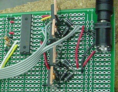
The circuit design and building is minimal for this project. The only necessary circuitry is to connect the unipolar stepper motor with the PIC, and connect the RS232 cable to the PIC. Please see the pages for the Unipolar Stepper Motor Driver Circuit and the PIC RS232 cable for more information on how they work and how to set them up.
PIC to L297 Connections
- Pin D0 is connected to Clock
- Pin D1 is connected to DIR
RS232 Cable Connections
- Orange Wire to RC6
- Ground to Ground
Overall Circuit
- The power cord near the PIC is for +5V power supply (left in picture), while the power cord on the other side of the board is for the +12V power supply (right in picture).
Mechanical Design
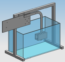
The main philosophy for the mechanical design is to build something reliable and adjustable. For the frame, we used Aluminum Fractional T-Slotted Framing System in order to make it strong and adjustable. The 1" by 1" beams are overkill for the loads that will be applied, and the weight of the frame will make sure it does not move. Using the T-Slotted Framing System allows for easy adjustment of the dimension of the frame, since all you have to do is undo a bolt in order to slide the connecting pieces to your location of choice. This allows one to easily change the size of the frame if one were to get a new fish tank. Also, it allows easy movement of the quarter circle that holds the arm up. The quarter circles allow you to adjust the angle of the arm and box in 10 degree increments by the adjustment of bolts with wing nuts. This allows great flexibility in the angles of the setup. All this is to make a system that is solid and will only move along the desired axis. The arm, box, quarter circle, and back plane for the motor are made out of 1/4" acrylic because it is a durable plastic material that will not effect the electric field emitted by the fish.
We used the laser in the shop to cut out the parts made of acrylic. Here are the CAD files for these parts in case you would like to edit or remake them:
arm.prt
box.prt
quarter_circle.prt
quarter_circle_large.prt
Results
Video of Automated Fish Refuge
The MATLAB program successfully converted user input into the delay times array and transferred this array to the PIC. We provided standard wave generators and give the user the ability to create any kind of motion desired. The transmission process can take up to a minute or two for long distances, but it works reliably. The PIC correctly read the array from the PC and converted it into motor control for the L297 chip. The motor performed well on a horizontal plane, but struggled at faster speeds. It also can struggle as the speed is increased while the arm is brought more vertical due to the added force of gravity. We chose the strongest unipolar stepper motor of our facilities, but this problem should be solved with a stronger motor. In either direction, the water resistance did not seem to have a noticeable affect on the motor.
Suggested Improvement
The main improvement we would suggest is to get a larger motor to allow faster movement and to improve vertical motion. Other than this the system responded accurately and reliably.
