Difference between revisions of "Guitar Tuning Project"
From Mech
Jump to navigationJump to search| Line 6: | Line 6: | ||
''' |
''' |
||
| ⚫ | |||
The whole system is shown in following figure. |
|||
| ⚫ | |||
| ⚫ | |||
goes into a unit gain voltage buffer and then converted into a DC signal after rectifying and low-pass filtering. This DC signal provides the volume information of the sound wave |
|||
| ⚫ | |||
to the PIC. The 2nd direction goes into a Band-Pass filter. Because the AC voltage signal from the preamplifier contains a lot of environmental noise as well as harmonic waves. |
|||
| ⚫ | |||
provides the amplitude of the sound wave to the PIC. The 2nd direction goes into a Band-Pass filter. Because the AC voltage signal from the preamplifier contains a lot of |
|||
| ⚫ | |||
| ⚫ | |||
| ⚫ | |||
comparator and becomes a square wave. This square wave is connected to the I/O pin of the PIC and the sound frequency is calculated by the PIC based upon this signal. |
comparator and becomes a square wave. This square wave is connected to the I/O pin of the PIC and the sound frequency is calculated by the PIC based upon this signal. |
||
With the calculated frequency of the current sound wave of the string, PIC compares it to the accurate frequency of the string stored in the program and generates corresponding |
With the calculated frequency of the current sound wave of the string, PIC compares it to the accurate frequency of the string stored in the program and generates corresponding |
||
control signals to control 6 DC motors using H bridges to tune the guitar string. |
control signals to control 6 DC motors using H bridges to tune the guitar string till the string's frequency approximates the standard frequency by a limited error (0.5Hz?) |
||
[[Image:GTTP_system_diagram.jpg]] |
[[Image:GTTP_system_diagram.jpg]] |
||
==Circuit Design and building== |
==Circuit Design and building== |
||
Revision as of 17:47, 6 December 2008
Guitar Tuning Project (GTTP)
Overview
Project Goal
      Achieve guitar tuning function. By manually plucking a guitar string, the system will determine whether the frequency is higher or lower than the set frequency.
      Based on the results, the system will tune the string's vibration frequency to the set frequency with a small error range (0.5Hz?).
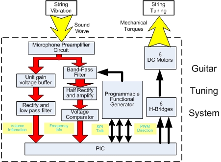
System Diagram
   The whole system is shown in following figure.
   The microphone and preamplifier convert the sound wave into a voltage wave and amplify it into AC voltage signal. This AC voltage signal goes into 2 directions. 1st direction
   goes into a unit gain voltage buffer and then converted into a DC signal after rectifying and low-pass filtering. This DC signal provides the volume information of the sound wave
   to the PIC. The 2nd direction goes into a Band-Pass filter. Because the AC voltage signal from the preamplifier contains a lot of environmental noise as well as harmonic waves.
   The band-pass filter can let a narrow band pass. The band-pass properties are controlled by the centering frequency set by a programmable waveform generator communicating with
   PIC. After the band-pass filter, the signal is a fairly clean sine wave signal. This signal experiences half-wave rectifying and amplifying. Later it goes into the voltage
   comparator and becomes a square wave. This square wave is connected to the I/O pin of the PIC and the sound frequency is calculated by the PIC based upon this signal.
   With the calculated frequency of the current sound wave of the string, PIC compares it to the accurate frequency of the string stored in the program and generates corresponding
   control signals to control 6 DC motors using H bridges to tune the guitar string till the string's frequency approximates the standard frequency by a limited error (0.5Hz?)