Difference between revisions of "Resistive Touchscreen"
| Line 27: | Line 27: | ||
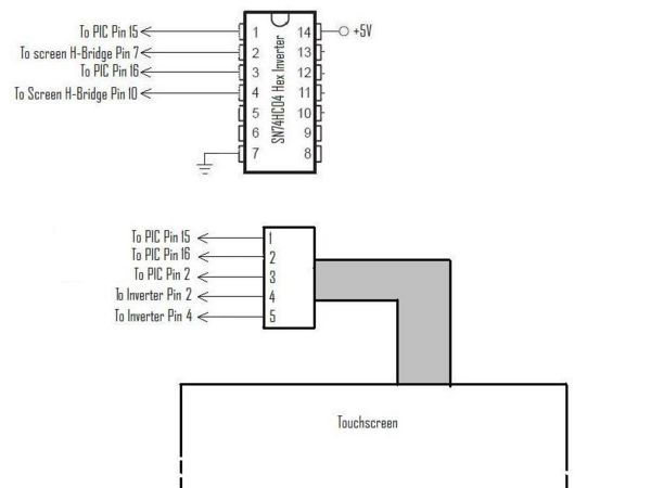
The voltage switching described above must be accomplished quickly and precisely (so as to avoid a shortage). One way to accomplish this is to permanently power opposite corners with +5V and ground, and then switch the other two according to an ISR. The alternating PIC output signal is sent to one of the corners, and the other one gets its opposite signal through an inverter. The inverter ensures that only one axis of the touch screen is activated at a time. |
The voltage switching described above must be accomplished quickly and precisely (so as to avoid a shortage). One way to accomplish this is to permanently power opposite corners with +5V and ground, and then switch the other two according to an ISR. The alternating PIC output signal is sent to one of the corners, and the other one gets its opposite signal through an inverter. The inverter ensures that only one axis of the touch screen is activated at a time. |
||
[[Image:Touchscreen-circuit-diagram.JPG|center|thumb|Touchscreen Circuit Diagram|600px]] |
|||
== References == |
== References == |
||
Revision as of 19:58, 20 March 2008
Overview
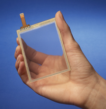
Resistive touchscreens are useful for measuring the position of an object on top of them, or as an interesting user interface feature. The Bergquist company sells them in a variety of sizes, ranging from 3.5 to 23 inches diagonal.
The 12.1 inch version was used in the Ball Balancing Challenge project. Its specifications can be found on the Bergquist website. The screens are transparent and are meant to be installed over an LCD display; however, they are also useful in a horizontal orientation (as in the "Ball Balancing Challenge" project) for sensing the position of an object resting above.
According to the technical specifications, the activation force for this touch screen is 50g. From experience, activation is more reliable with a heavier weight. The area of contact may also play a role in activation; metal balls rolling on the screen produced a slightly noisy signal which needed to be filtered for reliable use in a real-time system.
Implementation
A resistive touchscreen is essentially a large variable resistor. When a potential is put across two opposite sides of the touch screen, an output voltage can be read that is proportional to the touching distance between the activated sides. The Bergqist screen is a 5-wire resistive screen; its connections consist of four wires going to each of the corners (upper left, upper right, lower left, lower right) and one that goes to the surface. A potential across two opposite sides of the screen results in a gradient across the screen in that direction. When the surface is pushed in at a certain point, it forms a circuit, the output voltage of which can be read as an analog input into a PIC chip.
There are several ways to read a 5-wire resistive touchscreen. In the "Ball Balancing Challenge" project, the voltage gradient in one direction was created by placing +5 volts on two adjacent corners (for example the upper right and upper left) and grounding the other two. The position in the vertical direction was then read as proportional to the voltage on the middle (surface) wire.
Of course, this method only allows for the reading of one axis of the screen at a time. In order to read both the X and Y positions of the touchscreen, it is possible to use an interrupt service routine to switch rapidly between X and Y readings. For example, the +5V side can be switched between X and Y positions by alternating the voltage between the upper left (UL) and upper right (UR) corners and the upper left and lower left (LL) corners. Correspondingly, grounding will be switched between the lower left and lower right (LR) corners, and the upper right and lower right corners. This results in a type of square wave output on the screen wire, with its voltage representing the vertical and horizontal positions alternatively.
The voltage gradient in both the X and Y directions is linearly distributed from +5V to ground. Because the touch screens are typically rectangular, it may be necessary to multiply one of the readings by the screen's aspect ratio in order to create an equal coordinate system.
Circuit
The voltage switching described above must be accomplished quickly and precisely (so as to avoid a shortage). One way to accomplish this is to permanently power opposite corners with +5V and ground, and then switch the other two according to an ISR. The alternating PIC output signal is sent to one of the corners, and the other one gets its opposite signal through an inverter. The inverter ensures that only one axis of the touch screen is activated at a time.
References
1. Microphone - From Wikipedia, the free encyclopedia
2. Integrated Circuits for High Performance Electret Microphones

