Difference between revisions of "Digital inputs & outputs"
| Line 21: | Line 21: | ||
[[Image:Digitalio.gif|right]] |
[[Image:Digitalio.gif|right]] |
||
<b>Demo circuit for digital inputs and outputs</b> |
|||
The 4520 board has 32 1K resistors-to-ground built in, and spaces for 32 LEDs to be inserted, as shown in the circuit below You can see that the resistors are isolated from and have no effect on the PIC unless the LED is inserted. |
The 4520 board has 32 1K resistors-to-ground built in, and spaces for 32 LEDs to be inserted, as shown in the circuit below You can see that the resistors are isolated from and have no effect on the PIC unless the LED is inserted. |
||
At right is a demo circuit for digital input and digital output. Two LEDs have been inserted, and a pull-up switch and 4.7K pull-down resistor added. |
At right is a demo circuit for digital input and digital output. Two LEDs have been inserted, and a pull-up switch and 4.7K pull-down resistor added. |
||
Revision as of 20:18, 26 December 2007
Which pins are accessible on the 4520 prototyping board?
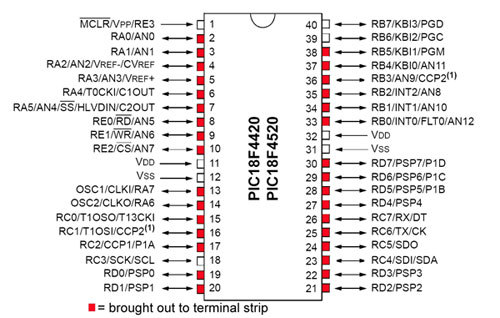
Most pins on the PIC are brought out to easily accessible lines on the 4520 board. Feel free to connect to the few others as well.
Do not drive any pin outside the range 0 to 5 volts, which can damage the PIC.
Most pins have several possible different input or output purposes, as evidenced by several names. Your software determines which purpose is in effect.
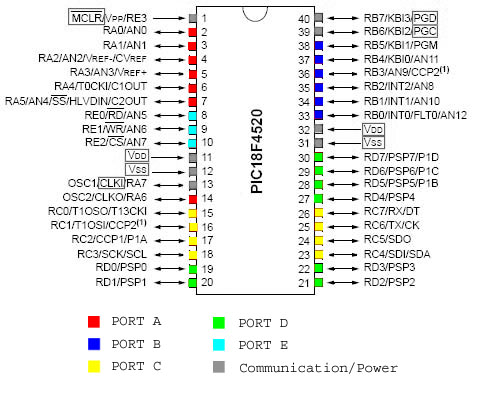
Digital I/O pins (five "ports")
With the exception of the positive voltage supply and ground pins, all pins on the PIC18F4520 can be used as digital I/O, however a few other pins (shown in gray below) are commonly utilized for communication instead of for digital I/O.
Demo circuit for digital inputs and outputs
The 4520 board has 32 1K resistors-to-ground built in, and spaces for 32 LEDs to be inserted, as shown in the circuit below You can see that the resistors are isolated from and have no effect on the PIC unless the LED is inserted.
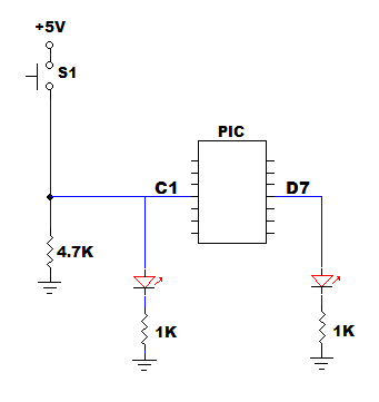
At right is a demo circuit for digital input and digital output. Two LEDs have been inserted, and a pull-up switch and 4.7K pull-down resistor added.
Pin C1 is intended as a digital input, and will be designated so in software. When pushbutton switch S1 is depressed, it brings input C1 high, and the left LED illuminates. Otherwise input C1 is held low by the 4.7K resistor to ground. (The LED and its resistor cannot be counted upon to hold input C1 low.)
Pin D7 is intended as a digital output. When the PIC drives it high, the right LED illuminates, and otherwise not.
Sample code
The code digitalio.c is a complete C program that will compile and run.
You can read or write one bit at a time, or a whole 8-bit port as a byte. The demo code illustrates the functions input_c() which reads the whole C port as a byte (and returns an int8 value) and output_d(value) which writes to the whole D port as a byte (and takes an int8 argument).
You can also read a single pin using input(PIN_C4) which returns 1 or 0. PIN_C4 and its siblings are defined in the 18f4520.h "include" file.
For output to a single pin, you can use output_high(PIN_D7) and output_low(PIN_D7) which drive pin D7 high or low, or you can set it to a value in a variable with output_bit(PIN_D7, value) where value is 1 or 0.
All of the above built-in functions include instructions to set the targeted port or pin to digital input mode or digital output mode. That takes a few extra microseconds every time the function is called. It is possible to turn this part of the function code off, if you take responsibility to set the direction of the port or pin yourself.
switch bounce - most mechanical switches "bounce" which means they open and close several times when activated, over a period of a few mS. If this is a problem for your software, there are a lot of ways to debounce switches electronically. Better, write your software so it doesn't get confused by multiple open-close cycles.


