Difference between revisions of "PIC Motor Control and Serial Port Example"
| Line 23: | Line 23: | ||
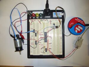
==Breadboard Layout== |
==Breadboard Layout== |
||
[[Image:C18_tutorial_motor_controller_breadboard. |
[[Image:C18_tutorial_motor_controller_breadboard.jpeg|thumb]] |
||
==HyperTerminal== |
==HyperTerminal== |
||
Revision as of 17:09, 2 September 2007
Introduction
In this application, we will use a PIC 18F4431 microcontroller to implement a closed-loop lead-lag compensator that controls the velocity of a motor with an encoder. This example will cover the use of:
- interrupts
- reading encoders
- pulse-width modulation
- USART (Universal Synchronous Asynchronous Receiver/Transmitter)
Every 20 milli-seconds, the PIC will sample the encoder and run the feedback control loop. The output from the control loop is then sent to the motor to try to match the motor's speed with the target speed. To set the target speed, commands are sent from a PC's serial port to the USART on the PIC. The PIC will also print the target speed and actual speed of the motor to the terminal window of the PC.
Project Files
Download the MPLAB project here.
This was compiled using MPLAB 7.6 and C18 3.12 (student version). If MPLAB has problems finding files or does not compile, it may be because the directories on your computer are set up differently. In this case, create a new project following these instructions, and copy in the source files.
Wiring Diagram
Wiring Diagram for the motor velocity controller example(PowerPoint)
