Difference between revisions of "PIC18F4520: Comparator"
m (→Sample Code) |
|||
| (2 intermediate revisions by the same user not shown) | |||
| Line 9: | Line 9: | ||
First include header file with definitions for specific PIC. |
First include header file with definitions for specific PIC. |
||
Set fuses. HS is type of external clock, low voltage |
Set fuses. HS is type of external clock, low voltage programming |
||
(LVP) is off, and the watchdog timer (WDT) is off. |
(LVP) is off, and the watchdog timer (WDT) is off. |
||
External clock frequency of 20 MHz is specified. |
External clock frequency of 20 MHz is specified. |
||
| Line 18: | Line 18: | ||
Begin main body of program. |
Begin main body of program. |
||
[[Image: |
|||
void main(void) { |
void main(void) { |
||
Setup the comparators C1 and C2. A0 is C1- and A3 is C1+. If C1+ > C1- |
Setup the comparators C1 and C2. A0 is C1- and A3 is C1+. If C1+ > C1-, |
||
C1 will output high (C1OUT = 1 = 5V). If C1- > C1+ C1 will output low. |
C1 will output high (C1OUT = 1 = 5V). If C1- > C1+ C1 will output low. |
||
A second comparator (C2) has been set up, but is not being utilized. |
A second comparator (C2) has been set up, but is not being utilized. |
||
| Line 41: | Line 41: | ||
} |
} |
||
} |
} |
||
===Circuit Diagram=== |
===Circuit Diagram=== |
||
[[Image:comparatorckt.jpg]] |
[[Image:comparatorckt.jpg]] |
||
Latest revision as of 09:15, 5 July 2007
Yet another function that the PIC18F4520 is capable of is that of an analog comparator. It is capable of running two separate analog comparators.
Available Pins
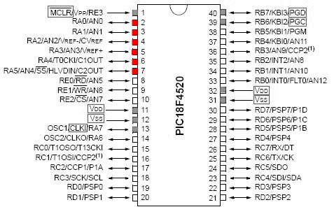
The PIC18F4520 allows A0-A3 (pins 2-5) to be used as analog comparator inputs, and A4-A5 (pins 6-7) to be used as comparator outputs. The red pins in the diagram below represent all pins available for use with an analog comparator. The grey pins are most commonly used for communication or power.
Comparator Example
Sample Code
Program to implement an analog comparator.
First include header file with definitions for specific PIC. Set fuses. HS is type of external clock, low voltage programming (LVP) is off, and the watchdog timer (WDT) is off. External clock frequency of 20 MHz is specified.
  #include <18f4520.h>
  #fuses HS,NOWDT,NOPROTECT,NOLVP
  #use delay(clock=20000000)
Begin main body of program.
void main(void) {
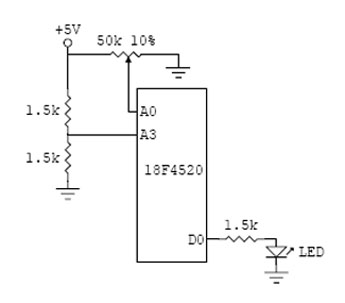
Setup the comparators C1 and C2. A0 is C1- and A3 is C1+. If C1+ > C1-, C1 will output high (C1OUT = 1 = 5V). If C1- > C1+ C1 will output low. A second comparator (C2) has been set up, but is not being utilized. See the header file 18F4520.h for all possible constants used in the setup_comparator() function.
setup_comparator(A0_A3_A1_A2);
Setup an infinite loop using a while statement.
while(TRUE) {
Check the output of the comparator and light an LED accordingly.
        if(C1OUT){
           output_low(PIN_D0);}
        else{
           output_high(PIN_D0);}
     }
  }

