Difference between revisions of "PIC16F684"
From Mech
Jump to navigationJump to search| Line 33: | Line 33: | ||
==Configuring I/O== |
==Configuring I/O== |
||
This section shows two sections of code that are used for setting up the I/O of the PIC. The INIT_IO function sets up the ports by setting their default value and their direction. The second function, INIT_ADC sets up the A/D converter. |
|||
<pre> |
<pre> |
||
INIT_IO |
INIT_IO |
||
BCF STATUS,RP0 ;Bank 0 |
|||
BANK0 |
|||
CLRF PORTA ;Init PORTA - initially set to LOW |
CLRF PORTA ;Init PORTA - initially set to LOW |
||
MOVLW B'000101' ;Set RA<0> as input |
MOVLW B'000101' ;Set RA<0> as input |
||
MOVWF TRISA ; and set RA<5:1> |
MOVWF TRISA ; and set RA<5:1> |
||
; as outputs |
|||
BANK1 |
|||
BSF STATUS,RP0 ;Bank 1 |
|||
CLRF PORTC ;Init PORTC - initially set to LOW |
CLRF PORTC ;Init PORTC - initially set to LOW |
||
MOVLW B'000000' ;Set RC<5:0> as outputs |
MOVLW B'000000' ;Set RC<5:0> as outputs |
||
| Line 48: | Line 50: | ||
MOVLW B'000001' |
MOVLW B'000001' |
||
MOVWF ANSEL ;Set AN<0> (RA<0>) to Analog input |
MOVWF ANSEL ;Set AN<0> (RA<0>) to Analog input |
||
; RA<5:1> remain digital I/O |
|||
RETURN |
RETURN |
||
INIT_ADC |
|||
BCF STATUS,RP0 ;Bank 0 |
|||
MOVLW B'00000001' ; Set output to left justified |
|||
MOVWF ADCON0 ; Select AN<0> (RA<0>) as input |
|||
; Internal Vref |
|||
; Start ADC ON |
|||
BSF STATUS,RP0 ;Bank 1 |
|||
CLRF ADCON1 |
|||
MOVLW B'00100000' ;Set Clock TAD to 1.6us (Fosc/32) |
|||
MOVWF ADCON1 |
|||
RETURN |
|||
</pre> |
|||
''Notice that the two following bits of code are equivalent:'' |
|||
<pre> |
|||
CLRF PORTA |
|||
</pre> |
|||
and |
|||
<pre> |
|||
MOVLW B'000000' |
|||
MOVWF PORTA |
|||
</pre> |
</pre> |
||
Revision as of 18:14, 11 July 2006
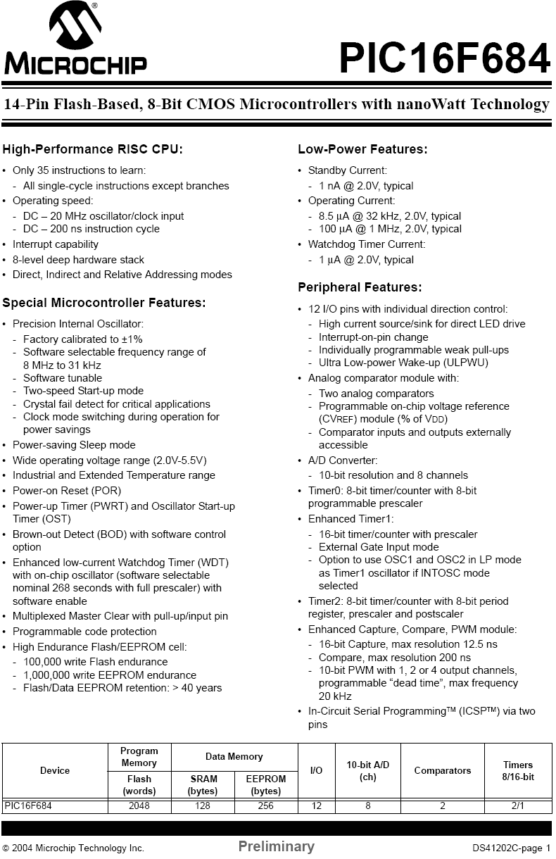
Overview
For a complete list of features, see this printout from the datasheet.
IMPORTANT: See PIC16F684 Registers for detailed information on registers.
Pinout

| Label | Description |
|---|---|
| + 5 V | |
| Ground | |
| External Voltage Reference | |
| PORTA/PORTC Programmable I/O | |
| A/D Channel | |
| External Interrupt Input | |
| PWM Output |


Initialization
Configuring I/O
This section shows two sections of code that are used for setting up the I/O of the PIC. The INIT_IO function sets up the ports by setting their default value and their direction. The second function, INIT_ADC sets up the A/D converter.
INIT_IO
	BCF 		STATUS,RP0 		;Bank 0
	CLRF 		PORTA 			;Init PORTA - initially set to LOW
	MOVLW 	B'000101'			;Set RA<0> as input
	MOVWF 		TRISA 			;	and set RA<5:1>
						;	as outputs

	BSF 		STATUS,RP0 		;Bank 1
	CLRF 		PORTC 			;Init PORTC - initially set to LOW
	MOVLW 	B'000000'			;Set RC<5:0> as outputs
	MOVWF 		TRISC

	CLRF		ANSEL			;Set all pins initially to digital I/O
	MOVLW	B'000001'
	MOVWF		ANSEL			;Set AN<0> (RA<0>) to Analog input
						;	RA<5:1> remain digital I/O
	RETURN

INIT_ADC
	BCF 		STATUS,RP0 		;Bank 0
        MOVLW   B'00000001'			; Set output to left justified
	MOVWF   	ADCON0			; Select AN<0> (RA<0>) as input
						; Internal Vref
						; Start ADC ON

	BSF 		STATUS,RP0 		;Bank 1
	CLRF		ADCON1
        MOVLW   B'00100000' 		        ;Set Clock TAD to 1.6us (Fosc/32)
        MOVWF   	ADCON1

	RETURN
Notice that the two following bits of code are equivalent:
CLRF PORTA
and
	MOVLW 	B'000000'
	MOVWF 		PORTA