Difference between revisions of "Pulse Width Modulation"
m |
m |
||
| Line 1: | Line 1: | ||
To control the speed of the motor, the switches of an H-bridge are opened and closed at different rates in order to apply different |
|||
| ⚫ | |||
are opened and closed at different rates in order to apply different |
|||
| ⚫ | |||
width modulation</B>. Let's look at the following diagrams:</P> |
|||
{| |
|||
<P><TABLE BORDER=1 WIDTH="75%" bordercolorlight="#FFFFFF" bordercolordark="#FFFFFF" bordercolor="#FFFFFF"> |
|||
|- |
|||
<TR> |
|||
| [[image:pwm1.jpg|300px]] |
|||
<TD WIDTH="55%"> |
|||
| [[image:pwm2.jpg|320px]] |
|||
<P><IMG SRC="pwm1.jpg" WIDTH=300 HEIGHT=230 X-CLARIS-USEIMAGEWIDTH X-CLARIS-USEIMAGEHEIGHT ALIGN=bottom></P> |
|||
|} |
|||
</TD> |
|||
<TD WIDTH="45%"> |
|||
| ⚫ | |||
<P><IMG SRC="pwm2.jpg" WIDTH=320 HEIGHT=230 X-CLARIS-USEIMAGEWIDTH X-CLARIS-USEIMAGEHEIGHT ALIGN=bottom></P> |
|||
</TD> |
|||
</TR> |
|||
</TABLE> |
|||
</P> |
|||
| ⚫ | |||
time. By switching quickly, we can create an average voltage across |
time. By switching quickly, we can create an average voltage across |
||
across the motor. The speed of the motor can be adjusted by changing |
across the motor. The speed of the motor can be adjusted by changing |
||
the pulse-width ratio: |
the pulse-width ratio: |
||
| ⚫ | |||
<P>of the voltage applied across its terminals.</P> |
|||
| ⚫ | |||
| ⚫ | |||
<P><IMG SRC="half_b.jpg" WIDTH=300 HEIGHT=230 X-CLARIS-USEIMAGEWIDTH X-CLARIS-USEIMAGEHEIGHT ALIGN=bottom></P> |
|||
| ⚫ | |||
| ⚫ | |||
| ⚫ | |||
| ⚫ | |||
| ⚫ | |||
| ⚫ | |||
[[image:half_b.jpg|300px]] |
|||
| ⚫ | |||
| ⚫ | |||
| ⚫ | |||
| ⚫ | |||
| ⚫ | |||
| ⚫ | |||
| ⚫ | |||
| ⚫ | |||
| ⚫ | |||
One of the possibilities is to use a L293D chip shown below: |
|||
[[image:L293.jpg|450px]] |
|||
<P><IMG SRC="L293.jpg" WIDTH=450 HEIGHT=357 X-CLARIS-USEIMAGEWIDTH X-CLARIS-USEIMAGEHEIGHT ALIGN=bottom></P> |
|||
When using a L293D chip, one of the concerns is heat sinking. It is because there are lots of power dissipation and we need to take |
|||
| ⚫ | |||
is because there are lots of power dissipation and we need to take |
|||
| ⚫ | |||
L293 to piece of metal or copper.</P> |
|||
Revision as of 13:00, 9 June 2006
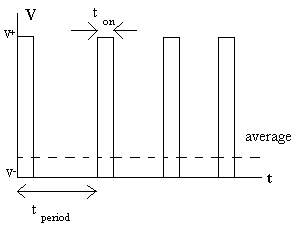
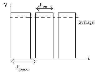
To control the speed of the motor, the switches of an H-bridge are opened and closed at different rates in order to apply different average voltages across the motor. This technique is called pulse width modulation. Let's look at the following diagrams:

|

|
In the above diagrams, V is the voltage across the motor and t is time. By switching quickly, we can create an average voltage across across the motor. The speed of the motor can be adjusted by changing the pulse-width ratio:
of the voltage applied across its terminals. If the motor only has to turn in 1 direction, we can just use a half bridge:
There are different ways to control the speed of a DC motor:
- switching from full positive to full negative
- full positive to open
- full negative to open
- braking by shorting
- free wheeling by leaving the circuit open.
One of the possibilities is to use a L293D chip shown below:
When using a L293D chip, one of the concerns is heat sinking. It is because there are lots of power dissipation and we need to take the heat away. One of the ways to do this is to connect pins of the L293 to piece of metal or copper.

