Difference between revisions of "Remote Controlled Wiitar"
NathanHirsch (talk | contribs) |
|||
| Line 1: | Line 1: | ||
[[Wiitar]] |
|||
==== Team Members ==== |
==== Team Members ==== |
||
Revision as of 22:29, 17 March 2010
Team Members
- Nathan Hirsch - Mechanical Engineering - Class of 2010
- George Randolph - Mechanical Engineering - Class of 2010
Overview
The goal of our project was to create a system that allows a user to use a remote control to play a guitar. The Remote Controlled Wiitar uses a Nintendo Wii Remote to control an array of solenoids and a motor that are capable of playing several different chords on a guitar.
Mechanical Design
Our design consisted of two major components. The solenoid bridge, which was responsible for depressing strings on the neck of the guitar, and the strumming bridge, which was responsible for strumming the strings of the guitar.
Solenoid Bridge
The solenoid bridge was constructed out of wood. Its table shape was designed to allow the neck of the guitar to fit under it, with enough clearance for several solenoids to be attached to the underside of the bridge.
Brackets made of eighth inch aluminum sheet metal were fashioned to mount the solenoids on the bridge. The brackets also included holes where elastic cable was attached. The elastic cable retracted the solenoids when they were not powered.
The solenoids were originally attached to bridge using nuts and bolts. Though this worked, it was difficult to attach the solenoids precisely enough to accurately depress the guitar strings. In the final design, Velcro was used instead of nuts and bolts. This allowed for more precise mounting of the solenoids on the solenoid bridge and facilitated easy reconfiguration of the solenoids into different chord shapes. A second solenoid bridge was added in the final design to allow additional notes to be fretted near the body of the guitar.
Strumming Bridge
The strumming bridge was also constructed out of wood. Two 2x4 legs were cut and connected at the top by a strip of plywood. The strumming bridge was designed to allow the body of the guitar to fit underneath, with enough clearance for a strumming arm to sweep across the strings.
The motor was attached at the center of the top of the strumming bridge using nuts and bolts. A thin plywood strip that served as a strummer was attached to the shaft of the motor using a set screw. The circular motion of the motor caused the strummer to be closer to the guitar strings in the center than the guitar strings on the outside. For this reason, a rotational spring was attached to one side of the strummer which deflected as it swept across the springs resulting in an even strum.
A hall effect sensor was mounted about six inches from the motor on the strumming bridge. A magnet was attached to the strummer that aligned with the hall effect sensor when the strummer was parallel to the ground. When these components were aligned, the hall effect sensor sent signals to the PIC, providing feedback on the position of the strummer.
Electrical Design
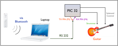
The circuity used to control the Wiitar is relatively simple. The figure to the right shows the basic concept of our project. The Wiimote communicates with a laptop via Bluetooth. Whenever a user shakes the Wiimote or presses a button on the Wiimote, a signal is sent to the computer. The computer then sends a message to the PIC via RS 232. The PIC takes those signals and outputs voltages to control the solenoids or strum the guitar, depending on the signal from the Wiimote.
Parts List
Fortunately, not very many electrical components are required to build the necessary circuitry to control the Wiitar. The parts that are needed can all be found in the mechatronics lab.
They are:
- PIC 32 microcontroller
- 100 Ω, 1 KΩ resistors and a 10 KΩ potentiometer
- 0.1 uF capacitor
- LM311N voltage comparator
- L293D H-Bridge
- Diodes
- Hall Effect Sensor
- NPN Darlington Pair Transistors
- LEDs
- Wiimote
- Computer with Bluetooth
Motor Circuit
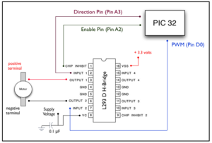
The motor that drive the strummer is operated by the PIC. The circuit to the right gives pin-outs and shows how to connect the motor to the PIC. Three pins on the PIC are used. A direction pin, an enable pin and a pin for PWM. The following table shows how they are related
| Direction | PWM | Motion |
|---|---|---|
| 0 | 0 | Brake |
| 0 | 1 | Forward |
| 1 | 0 | Reverse |
| 1 | 1 | Brake |
The H-Bridge we used to drive the motor was an L293D. It's data sheet can be found here
Code
Results and Reflections
When we first envisioned the Remote Controlled Wiitar, we wanted to create a system that could play many different chords and songs very easily. We originally wanted an array of eighteen solenoids (one for each string on the first three frets) that would allow us to play dozens of chords and thousands of songs. Our final project had only six solenoids and could play a grand total of three chords.
Despite a creating a system that was simpler than intended, our project was very successful. At the beginning of the quarter, we had limited knowledge of electronic circuitry, no knowledge of microcontrollers, and almost no experience programming in C. Using knowledge that we gained throughout the quarter, we were able to design and build a system that was fun for anyone to use and could control a guitar using a Wii Remote.
There are many things that we could have done to improve our project. Perhaps the largest problem we encountered was the fact that the smallest solenoids available to us were too large to fit more than a couple solenoids per fret on the guitar. This was the main reason for the simplification of the solenoid array from eighteen solenoids to only six. To fix this problem, we could have positioned the solenoids away from the neck of the guitar and used a system of levers to push the guitar strings. This would have allowed us to depress more strings and enabled us to play more chords.
Another improvement would be made to the strummer. We wanted to be able to strum the strings up and down, but our final system could only strum down (from the lowest string to the highest). This was primarily an issue of feedback. We decided early in our project that we did not need the resolution of an encoder to control the strumming bar, so we opted for a hall effect sensor instead. We quickly realized that there was significant overshoot when using the feedback from the hall effect sensor that prevented us from being able to strum the strings in both directions. Had we used an encoder, we would have had better control over the position of the strummer and we would have been able to strum both up and down.
There was also talk of adding a "player piano" mode to our system. This mode would have had the PIC automatically play a song using timed strums and chord changes without input from a Wii Remote. Due to a number of other issues we were having with our project, we did not have time to add the player piano mode. This would have been a great addition to the system that could have really demonstrated its capabilities.
Over the course of building our Wiitar, we burnt out one PIC. We noticed that when the PIC was powered on it was getting very hot, even when it was completely disconnected from the rest of our circuit. We could not find the cause of this, but we suspect that something on the PIC board was shorting. When a new PIC was placed into the circuit, the system returned to functioning properly.
Despite having little experience in electronic design or programming, most of our issues were a result of mechanical problems. The underlying circuitry and code functioned exactly as originally planned. Coding entirely in C, we were able to receive signals from a Wii Remote on a computer, relay those signals to our PIC using RS232 communication, and have the PIC depress appropriate guitar strings and strum a guitar. Learning how to do all of this and applying it to our project was our greatest success.


