Difference between revisions of "PIC32MX: Interfacing with Force Sensors from a Scale"
JoshuaPeng (talk | contribs) |
NickMarchuk (talk | contribs) |
||
| (31 intermediate revisions by 2 users not shown) | |||
| Line 1: | Line 1: | ||
== Original Assignment == |
|||
'''Do not erase this section!''' |
|||
Your assignment is to use four analog inputs to continuously read four force sensors taken from a bathroom scale, and to display them on a PC screen as bars whose length corresponds to the force at the sensors. You will use Processing for the PC data acquisition and graphics. |
|||
== Overview == |
== Overview == |
||
A BME Senior Design project group is developing a device to measure the weight shifting ability of a child with Cerebral Palsy. The end goal is develop |
A BME Senior Design project group is developing a device to measure the weight shifting ability of a child with Cerebral Palsy. The end goal is to develop a video game that is controlled by the child shifting their weight. Hopefully this device will allow the children to improve their balance while having fun playing a video game. |
||
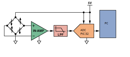
Our portion of the project involves designing the hardware to read the signals from 4 load cells and writing code to read in the load values to a PIC 32 microcontroller which is then sent to a PC via RS232. Additionally we developed an interface for the PC that visually represents the collected data in a useful and intuitive format. |
Our portion of the project involves designing the hardware to read the signals from 4 load cells and writing code to read in the load values to a PIC 32 microcontroller which is then sent to a PC via RS232. Additionally we developed an interface for the PC that visually represents the collected data in a useful and intuitive format. |
||
| Line 42: | Line 36: | ||
If it reads the character 'p' from volatile unsigned char data, which is sent from Processing when the 'zero out sensors' button is pressed, then it will record the initial values of the four sensors. |
If it reads the character 'p' from volatile unsigned char data, which is sent from Processing when the 'zero out sensors' button is pressed, then it will record the initial values of the four sensors. |
||
The full code can be found [http://hades.mech.northwestern.edu/images/ |
The full code can be found [http://hades.mech.northwestern.edu/images/9/9b/PIC_scale_convert.zip here]. |
||
'''"main.c"''' |
'''"main.c"''' |
||
| Line 81: | Line 75: | ||
== Processing Code == |
== Processing Code == |
||
'''The Processing portion of our lab involves 4 |
'''The Processing portion of our lab involves 4 visible sections:''' |
||
1. Colorbars, ''colorbars();'' |
1. Colorbars, ''colorbars();'' |
||
| Line 89: | Line 83: | ||
2. XY-Plot, ''xyplot();'' |
2. XY-Plot, ''xyplot();'' |
||
continuously displays the x- and y- position of the center of balance calculated between all 4 sensors with a dot on a xy-coordinate plane. So, if the person shifts |
continuously displays the x- and y- position of the center of balance calculated between all 4 sensors with a dot on a xy-coordinate plane. So, if the person shifts his weight to the right side of scale, then the dot will move to the right in the x direction. If the person shifts his weight to the front of the sensor, then the dot will move up in the y direction. The corners represent one sensor at it's maximum amplitude (of 255) with the rest of the sensors at zero amplitude. |
||
3. X-position vs. Time ''(not a separate function)'' |
3. X-position vs. Time ''(not a separate function)'' |
||
continuously plots a dot for the x-position along a time axis. This plot will be useful to see how much the person shifts his/her weight to the left or right ( |
continuously plots a dot for the x-position along a time axis. This plot will be useful to see how much the person shifts his/her weight to the left or right (lateral shift) over time. Due to the window size and the speed of processing, the points will be plotted over a time period of about 20 seconds. |
||
4. Y-position vs. time ''(not a separate function)'' |
4. Y-position vs. time ''(not a separate function)'' |
||
continuously plots a dot for the y-position along a time axis. This plot will be useful to see how much the person shifts his/her weight forward or backwards ( |
continuously plots a dot for the y-position along a time axis. This plot will be useful to see how much the person shifts his/her weight forward or backwards (anteroposterior shift) over time. The code for this section is essentially the same as the x-position but edited to show y-position. |
||
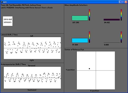
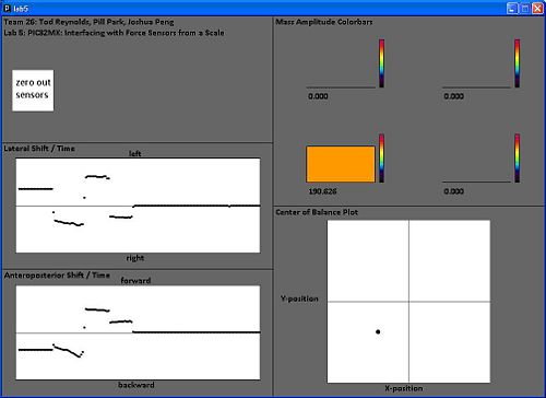
'''Screenshots:''' exerting force on the sensors in a circular pattern (left) and exerting force on one sensor at a time (right). |
|||
[[Image:Circle.jpg | 500px]] [[Image:loadon1sensor.jpg | 500px]] |
|||
| Line 117: | Line 116: | ||
4. Button to zero out force sensors |
4. Button to zero out force sensors |
||
Adds a button to zero out the force sensors. Noise displaces our dot in the xy-plot from the center when we first turn on our circuit. There is an interrupt function in the main.c file that will do the "zeroing out" and output altered values once this button is pressed. The code for this button was taken from ME333: Motor Control |
Adds a button to zero out the force sensors. Noise displaces our dot in the xy-plot from the center when we first turn on our circuit. There is an interrupt function in the main.c file that will do the "zeroing out" and output altered values once this button is pressed. The code for this button was taken from ME333 Lab 4: Motor Control, written by Nick Marchuk. |
||
''' |
'''Notes on relative amplitude range and mapping:''' |
||
| ⚫ | Our code was written with the assumption that the inputs from the PIC (that initially comes from the 4 force sensors) will come in the form of a 4x1 array. It does not actually arrive in that form from the PIC, it actually arrives as a string of floats separated by spaces ending with a new line. The new line is deleted and the floats are extracted out, normalized between 0-255, and put into the "mass" array. All of the normalization, window dimension parameters, rectangle dimensions, etc. were set up with the 0-255 range and 1000x700 window size in mind. So if the values are not between 0-255 or the window size is altered, almost all of following code will be messed up. The x-position vs. time and y-position vs. time plots are not implemented as independent functions. The code for these plots are found at the very end of colorbars();. |
||
One of the global variables, mapping integer "m," determines the sensitivity of the sensors. Our potentiometers are tuned to output a miniscule positive voltage difference which is amplified by 675. The resulting value falls within our initial range of 0-m (default: 0-511) which is then mapped to a floating-point number range 0-255. We found that the default initial range of 0-511 (m = 511) works well for adults standing on the scale. For adults using their hands to exert force on the scale, the range 0-200 (m = 200) is more suitable. Thus, as m is decreased, the sensitivity is increased. This mapping variable can be altered for each individual user, especially cerebral palsy patients, for which this scale is designed. |
|||
==Next Steps== |
|||
1. Develop a printed circuit board that contains all amplification circuitry, the microcontroller, and tunning circuits. Additionally, redesign the tunning circuit so that it is more robust. |
|||
2. Find a formula(hopefully linear) that equates the voltages seen from the sensors to mass. This can be done by using a few objects whose mass's are known. |
|||
3. Develop a chart that details what the "m" mapping variable value should be for a user's body weight and configure the scale to automatically adjust the m value when a user steps on the scale. |
|||
4. Also, make the colorbars or plot dots change to a certain color and/or have the computer play a sound when a certain mass amplitude value on a sensor has been breached. This may be useful for cerebral palsy patients that are being trained to maintain balance. |
|||
| ⚫ | Our code was written with the assumption that the inputs from the PIC (that initially comes from the 4 force sensors) will come in the form of a 4x1 array. It does not actually arrive in that form from the PIC, it actually arrives as a string of floats separated by spaces ending with a new line. The new line is deleted and the floats are extracted out, normalized between 0-255, and put into the "mass" array. All of the normalization, window dimension parameters, rectangle dimensions, etc. were set up with the 0-255 range and 1000x700 window size in mind. So if the values are not between 0-255 or the window size is altered, almost all of following code will be messed up. The x-position vs. time and y-position vs. time plots are not implemented as independent functions. The code for these plots are found at the very end of colorbars();. |
||
The full Processing code can be found here. |
|||
| ⚫ | |||
==Files== |
|||
| ⚫ | |||
The full Processing code can be found [http://hades.mech.northwestern.edu/images/5/54/Processing_lab5.zip here]. |
|||
| ⚫ | |||
| ⚫ | |||
'''Screenshots''' |
|||
Latest revision as of 14:21, 1 March 2010
Overview
A BME Senior Design project group is developing a device to measure the weight shifting ability of a child with Cerebral Palsy. The end goal is to develop a video game that is controlled by the child shifting their weight. Hopefully this device will allow the children to improve their balance while having fun playing a video game.
Our portion of the project involves designing the hardware to read the signals from 4 load cells and writing code to read in the load values to a PIC 32 microcontroller which is then sent to a PC via RS232. Additionally we developed an interface for the PC that visually represents the collected data in a useful and intuitive format.
Circuit
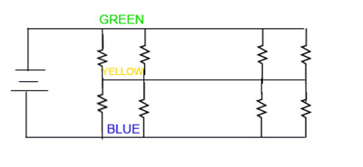
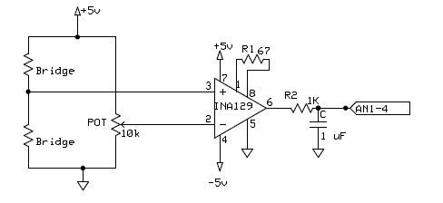
Each load sensor acts as a half bridge rectifier. When a potential difference is applied across the bridge, changes in load can be measured by sensing the voltage change at the middle of the bridge. This voltage change will be on the order of a few microvolts for most load cells.
In order to read this very small change in voltage you need to use an [Instrumentation Amplifier]. Instrumentation amplifiers read in two voltages and multiply the difference by a value specified by an external gain resistor.
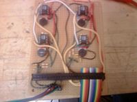
To complete the second half of the Wheatstone bridge a potentiometer is used. This potentiometer can be tuned to match the voltage produced by the load cell when no weight is applied. Therefore as more weight is applied the voltage out of the amplifier will increase until saturation of the amp is reached. This tunning is very important and can be time consuming because an initial offset of a few millivolts can force the amplifier to saturation.
The signal that leaves the amp is fairly noisy so a low pass filter is used to smooth out the signal that is sent to the ADC.
PIC Code
The purpose of this code is to take the input signals (amplified voltage differences) from the 4 individual force sensors on the scale and output a string of 4 floats separated by spaces ending with a new line. This string will be sent out using RS232 and deciphered by Processing.
ADC: In order to use the Analog-to-Digital converter embedded in PIC, we used Nick’s example, PIC32MX: Analog Input. Copy all the lines in this link except for the infinite while loop. However, you want to have four analog inputs for this project therefore you will need to change the number of analog inputs since this example only uses two analog inputs. Do the following modifications in order to have four analog inputs.
- define PARAM2, you need four samples, so change ADC_SAMPLES_PER_INT_2 --> ADC_SAMPLES_PER_INT_4.
- define PARAM4, you also need to enable AN3 and AN4 as well with AN1 and AN2,
- define PARAM5, you don’t want to skip AN3 and AN4, so remove these two inputs from this parameter.
Interrupt Handler: This function will affect our code only if the PIC receives a data from the processing via RS232 cable. If the interrupt occurs, it will first check whether the receive input interrupt flag was generated or transmit output interrupt flag was generated. And if it was the receive input interrupt, then it will save the value it received to the volatile unsigned char data, which we declared as a global variable. Then, the next line of code is a switch statement. If it reads the character 'p' from volatile unsigned char data, which is sent from Processing when the 'zero out sensors' button is pressed, then it will record the initial values of the four sensors.
The full code can be found here.
"main.c"
Main Function
int main(void)
{
	int	pbClk;

	// Sets the B port to Analog Input
        AD1PCFG = 0xFFFF;

	// Configure the proper PB frequency and the number of wait states
	pbClk = SYSTEMConfigPerformance(SYS_FREQ);

	// Allow vector interrupts
	INTEnableSystemMultiVectoredInt();
	mInitAllLEDs();
	initUART2(pbClk);
	initADC();

	while(1)
	{
        // read each sensor, subtract zero state value,
	top_left= ReadADC10(0)-top_left_initial;
	top_right= ReadADC10(1)-top_right_initial;
	bottom_left= ReadADC10(2)-bottom_left_initial;
	bottom_right= ReadADC10(3)-bottom_right_initial;

//Send to PC via RS232
	sendDataRS232();
        }

} //end main
Processing Code
The Processing portion of our lab involves 4 visible sections:
1. Colorbars, colorbars();
continuously displaying the force applied onto each force sensor by using 4 bars that will grow or shrink depending on the amplitude of mass (force). The bars will also show the amplitude of the mass by changing colors. When 0 or little force is applied, then corresponding bar is black colored, at the max force, the bar is orchid (pink) colored.
2. XY-Plot, xyplot();
continuously displays the x- and y- position of the center of balance calculated between all 4 sensors with a dot on a xy-coordinate plane. So, if the person shifts his weight to the right side of scale, then the dot will move to the right in the x direction. If the person shifts his weight to the front of the sensor, then the dot will move up in the y direction. The corners represent one sensor at it's maximum amplitude (of 255) with the rest of the sensors at zero amplitude.
3. X-position vs. Time (not a separate function)
continuously plots a dot for the x-position along a time axis. This plot will be useful to see how much the person shifts his/her weight to the left or right (lateral shift) over time. Due to the window size and the speed of processing, the points will be plotted over a time period of about 20 seconds.
4. Y-position vs. time (not a separate function)
continuously plots a dot for the y-position along a time axis. This plot will be useful to see how much the person shifts his/her weight forward or backwards (anteroposterior shift) over time. The code for this section is essentially the same as the x-position but edited to show y-position.
Screenshots: exerting force on the sensors in a circular pattern (left) and exerting force on one sensor at a time (right).
Other Important Functions:
1. Communication between the PC (Processing) and the PIC via RS232, void initSerial();
The purpose of InitSerial(); is to open a serial port on the PC and communicate with the PIC32. The code found here is essentially a modification of the ME333 Lab 4: Motor Control Processing code written by Nick Marchuk.
2. X-position, float xposition();
Calculates the x-position based on the contribution of each force sensor output and returns the resulting float value.
3. Y-position, float yposition();
Calculates the y-position based on the contribution of each force sensor output and returns the resulting float value.
4. Button to zero out force sensors
Adds a button to zero out the force sensors. Noise displaces our dot in the xy-plot from the center when we first turn on our circuit. There is an interrupt function in the main.c file that will do the "zeroing out" and output altered values once this button is pressed. The code for this button was taken from ME333 Lab 4: Motor Control, written by Nick Marchuk.
Notes on relative amplitude range and mapping:
Our code was written with the assumption that the inputs from the PIC (that initially comes from the 4 force sensors) will come in the form of a 4x1 array. It does not actually arrive in that form from the PIC, it actually arrives as a string of floats separated by spaces ending with a new line. The new line is deleted and the floats are extracted out, normalized between 0-255, and put into the "mass" array. All of the normalization, window dimension parameters, rectangle dimensions, etc. were set up with the 0-255 range and 1000x700 window size in mind. So if the values are not between 0-255 or the window size is altered, almost all of following code will be messed up. The x-position vs. time and y-position vs. time plots are not implemented as independent functions. The code for these plots are found at the very end of colorbars();.
One of the global variables, mapping integer "m," determines the sensitivity of the sensors. Our potentiometers are tuned to output a miniscule positive voltage difference which is amplified by 675. The resulting value falls within our initial range of 0-m (default: 0-511) which is then mapped to a floating-point number range 0-255. We found that the default initial range of 0-511 (m = 511) works well for adults standing on the scale. For adults using their hands to exert force on the scale, the range 0-200 (m = 200) is more suitable. Thus, as m is decreased, the sensitivity is increased. This mapping variable can be altered for each individual user, especially cerebral palsy patients, for which this scale is designed.
Next Steps
1. Develop a printed circuit board that contains all amplification circuitry, the microcontroller, and tunning circuits. Additionally, redesign the tunning circuit so that it is more robust.
2. Find a formula(hopefully linear) that equates the voltages seen from the sensors to mass. This can be done by using a few objects whose mass's are known.
3. Develop a chart that details what the "m" mapping variable value should be for a user's body weight and configure the scale to automatically adjust the m value when a user steps on the scale.
4. Also, make the colorbars or plot dots change to a certain color and/or have the computer play a sound when a certain mass amplitude value on a sensor has been breached. This may be useful for cerebral palsy patients that are being trained to maintain balance.
Files
The full Processing code can be found here.
A full zip file containing the PIC code, Processing code, images, screenshots can be found here.
A link to a demonstration video of the force sensing scale can be found here.
