Difference between revisions of "Indoor Localization System"
(→Bugs) |
Jonathan Lee (talk | contribs) m (Undo revision 14310 by Jonathan Lee (Talk)) |
||
| (24 intermediate revisions by 3 users not shown) | |||
| Line 1: | Line 1: | ||
'''This page is obsolete and should be used for reference only. Go to [[Machine Vision Localization System]]''' |
|||
== Motivation == |
== Motivation == |
||
| Line 99: | Line 100: | ||
'+' |
'''+''' and '''-''': Binary Thresholding: To adjust the black and white levels, use the + and - keys to increase or decrease the threshold. Ideally, this should be increased as high as possible without producing random noise. |
||
'[' |
'''[''' and ''']''': Target Size: This measurement corresponds to the maximum distance between dots in a target. If your 3x3 grid is spaced at 1 inch intervals, this value is ideally 1 inch. This parameter should be decreased as much as possible before targets are lost. If this parameter is too large, the algorithm will blend the patterns together. |
||
'z' |
'''z''' and '''x''': Area Thresholding: This parameter controls the desired size of 'dots'. This is used to remove relatively large or small noise artifacts. This parameter should be as large as possible to remove specular noise. |
||
== Algorithm Design == |
== Algorithm Design == |
||
| Line 155: | Line 156: | ||
===Real-time algorithm source:=== |
===Real-time algorithm source:=== |
||
*[[media:TrackSysV1 6 20 08.zip|'''TrackSysV1_6_20_08.zip''']] '''(Real-time tracking system code)''' |
|||
http://hades.mech.northwestern.edu/wiki/images/8/85/TrackSysV1_6_20_08.zip |
|||
====Bugs==== |
====Bugs==== |
||
# "Select Capture Devices," CameraID should be CaptureID. |
# Line 694. "Select Capture Devices," '''CameraID''' should be '''CaptureID'''. |
||
# Program will hang if "target_classifiers.txt" is not found. |
# Program will hang if "target_classifiers.txt" is not found. |
||
# Program will hang if "world_coord_template.jpg" is not found. |
|||
# World Coord Template will not redraw. |
# World Coord Template will not redraw. |
||
# Memory leak: Line 1158. '''cvFindContours''' is called in the '''while(1)''' loop, but the memory storage is never cleared. Use '''cvClearMemStorage()''' before '''cvFindContours()''' to discard old data. |
|||
# Memory leak: Line 1118,1279. '''targets_temp''' is pointing to a new object, but is reassigned on line 1279. Comment out the '''for''' loop on lines 1118-1123. |
|||
# Camera Calibration does not seem to be robust. |
|||
# '''camScan''' flags are never rearmed. |
|||
# Line 1625: There is no check to see if '''temp->ID''' has been assigned to -1 in the previous loop. |
|||
# In calibration, double subU = cvmGet(&U, i, 0);double subV = cvmGet(&U, i+1, 0); should be i*2? |
|||
# Camera calibration is broken. |
|||
# Function '''LoadTargetData()''' will not read the last data point because it can't find a comma at the end of the line. |
|||
# In '''LoadTargetData()''', current->num_idd = idd_num; should be new_classifier->num_idd = idd_num; ? |
|||
# In '''LoadTargetData()''', a newline at the end of the '''target_classifiers.txt''' will get read in, making the linked list 1 node longer than it should be. |
|||
===Pre-processing program source with final patterns:=== |
===Pre-processing program source with final patterns:=== |
||
*[[media:TrackSysV1_6_20_08.zip|'''TrackSysV1_6_20_08.zip''']] '''(Target patterns and preprocessor)''' |
|||
http://hades.mech.northwestern.edu/wiki/images/f/fe/TrackSysTraining_6_20_08.zip |
|||
**For actual images of the target patterns: '''TrackSysTraining(folder) >> images(folder) >> FinalSet(folder)>>1,2,3,...,24''' |
|||
[[Category:SwarmRobotProject]] |
|||
Latest revision as of 13:14, 8 September 2009
This page is obsolete and should be used for reference only. Go to Machine Vision Localization System
Motivation
For relatively simple autonomous robots, knowing an absolute position in the world frame is a very complex challenge. Many systems attempt to approximate this positioning information using relative measurements from encoders, or local landmarks. Opposed to an absolute system, these relativistic designs are subject to cumulating errors. In this design, the positioning information is calculated by an external computer which then transmits data over a wireless module.
This system can be envisioned as an indoor GPS, where positioning information of known patterns is transmitted over a wireless module available for anyone to read. Unlike a GPS, this vision system is designed for indoor use on a smaller scale (in/cm).
Overview of Design
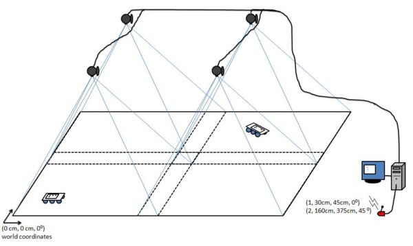
This system uses four standard webcams to locate known patterns in a real time image, and transmit positioning information over a serial interface. This serial interface is most often connected to a wireless Zigbee® module. The cameras are mounted in fixed positions above the target area. The height of the cameras can be adjusted to increase either the positioning resolution or the area of the world frame. These constraints are a function of the field of view of the lenses. Below is a diagram illustrating this system’s basic setup.
Here, we can see the four cameras are mounted rigidly above the world frame. Note that the cameras actual placement must have an overlap along inside edges at least the size of one target. This is necessary to ensure any given target is at least fully inside one camera’s frame.
Goals
• To provide real-time (X, Y, θ) position information to an arbitrary number of targets (<20) in a fixed world frame using a home-made computer vision system.
• Maximize throughput and accuracy
• Minimize latency and noise
• Easy re-calibration of camera poses.
• Reduced cost (as compared to real-time operating systems and frame grabbing technology)
Tools Used
Software
• IDE: Microsoft Visual C++ Express Edition – freeware (http://www.microsoft.com/express/default.aspx)
• Vision Library: Intel OpenCV – open source c++ (http://sourceforge.net/projects/opencvlibrary/)
• Camera Capture Library: VideoInput – open source c++ (http://muonics.net/school/spring05/videoInput/)
Hardware
• Four Logitech QuickCam Communicate Deluxe USB2.0 webcams
• One 4-port USB2.0 Hub
• Computer to run algorithm
How to Use The System
Camera Setup
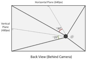
The four cameras used were standard Logitech QuickCam Communicate Deluxes. For future use, the videoInput library used is very compatible and works with most capture devices. As measured, the viewing angle (from center) of the Logitech cameras was around 30 degrees (horizontal plane) and 25 degrees (vertical plane).
Before attaching the cameras, several considerations must be made.
1. Choose a desired ALL WHITE area to cover. ***IMPORTANT: If you want to be able to cover an continuous region, the images as seen by the cameras must overlap to ensure a target is at least fully visible in one frame of a camera*** Keep in mind that there is a trade-off between area, and resolution. In addition, the size of the patterns will have to be increased above the threshold of noise.
2. Ensure that the cameras are all facing the same direction. As viewed from above, the "top" of the cameras should all be facing the same direction (N/S/E/W). For future use, if these directions must be variable, the image reflection and rotation parameters can be adjusted in software (though this has not been implemented).
3. Try to mount the cameras as "normal" as possible. Although the camera calibration should determine the correct pose information, keeping the lenses of the cameras as normal as possible will reduce the amount of noise at the edges of the images.
Computer Setup
In the current implementation, this system has been developed for a Windows based computer (as restricted by the videoInput library). The system should run in Windows XP or Vista. To setup the computer to develop and run the software, the three required libraries must be installed.
1. Download and install the Logitech QuickCam Deluxe Webcam Drivers - http://www.logitech.com/index.cfm/435/3057&cl=us,en
2. Download and install Microsoft Visual Studio Express - http://www.microsoft.com/express/default.aspx
3. Download and install Microsoft Windows Platform SDK - http://www.microsoft.com/downloads/details.aspx?FamilyId=0BAF2B35-C656-4969-ACE8-E4C0C0716ADB&displaylang=en
4. Download and install Microsoft DirectX 9+ SDK - http://www.microsoft.com/downloads/details.aspx?FamilyId=572BE8A6-263A-4424-A7FE-69CFF1A5B180&displaylang=en
5. Download and install Intel OpenCV Library - http://sourceforge.net/projects/opencvlibrary/
6. Download and install the videoInput Library - http://muonics.net/school/spring05/videoInput/
7. Download the program as listed at the end of this page.
How to Run the Program
Open the project file as listed at the bottom of this page. Compile and run the program from Visual Studio or as in the build folder.
Once running, the program should outline what is necessary to setup and operate. The steps are also outlined below.
1. Connect to cameras. You will have to type the 4 numbers (in the command prompt) associated with the correct capture devices. Most likely, these will be 0-3.
2. Orient cameras. To correlate an individual camera with its position overhead, you must click once on the quadrant corresponding to the live camera image shown. You will click 4 times, once for each camera.
3. Check. Once you have selected the quadrants for each camera, you can look at the combined image in the main window to make sure the cameras are positioned correctly and that the background is all white. Press the Enter button in the main window to continue.
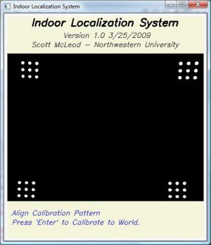
4. Enter Calibration Parameters. To calibrate the cameras to world coordinates, you must type in numbers relating to the patterns positions. Ensure that you place the patterns down in a rectangular fashion (in the world frame not the images). The numbers are typed into the command prompt. You will enter three numbers as measured (they may be in inches or cm or whatever unit desired).
5. Capture Calibration Pattern. To calibrate the cameras, you must now take a picture of the patterns as viewed by ALL FOUR Cameras. By now, you should have the calibration pattern arranged on the surface. ****ENSURE THAT THE ONLY VISIBLE OBJECTS IN THE IMAGE ARE THE DOTS FROM THE CALIBRATION PATTERN**** The program is designed to calibrate to the first 9 dots in each image that it sees. If there are more than 9 dots in ANY camera image, the program will correlate the FIRST 9 dots to the measured positions. If one camera sees more than one calibration pattern (fully or partially) it will NOT calibrate properly. You may adjust the threshold with the + and - keys dynamically to remove any specular noise.
6. Remove the Calibration Pattern. Now remove or cover up the calibration dots and press 'Enter' to proceed to the real time operation of the program. To quit the program, Press 'Esc'.
Real time Adjustable Parameters
During the real time operation of the program, many of the algorithm parameters will need to be adjusted for the current setup. These parameters and keys are listed below.
+ and -: Binary Thresholding: To adjust the black and white levels, use the + and - keys to increase or decrease the threshold. Ideally, this should be increased as high as possible without producing random noise.
[ and ]: Target Size: This measurement corresponds to the maximum distance between dots in a target. If your 3x3 grid is spaced at 1 inch intervals, this value is ideally 1 inch. This parameter should be decreased as much as possible before targets are lost. If this parameter is too large, the algorithm will blend the patterns together.
z and x: Area Thresholding: This parameter controls the desired size of 'dots'. This is used to remove relatively large or small noise artifacts. This parameter should be as large as possible to remove specular noise.
Algorithm Design
Overview
To identify different objects and transmit position and rotation information a 3x3 pattern of black circles is used for each object. To create both position and orientation, each pattern must have at least 3 dots in a rotationally invariant configuration. The algorithm identifies unique patterns by assuming dots within a certain adjustable distance are part of the same pattern. It then identifies which pattern is associated with the dots via a comparison of the relative distances between the dots.
Pre-Processing
Target Classification
Before the system is executed in real time, two tasks must be completed. The first is pre-processing the possible targets to match (the patterns of 3x3 dots). This is done by first creating a subset of targets from the master template. Each target must be invariant in rotation, reflection, scale and translation. A set of targets has been included in the final project, with sample patterns. When the program is executed in real time, it will only identify targets from the trained subset of patterns.
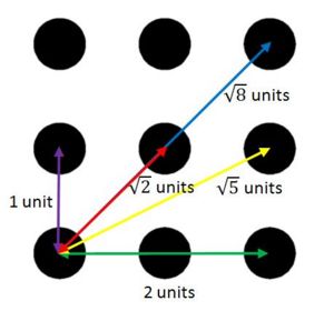
When the targets are pre-processed, unique information is recorded to identify each pattern. In particular, the algorithm counts the number of dots and the relative spacing between each dot. In this sense, the pattern is identified as a unique number (corresponding to the order of target patterns in the image directory), the number of dots in the pattern, and the normalized spacing between each dot. Since the pattern is a fixed 3x3 grid, the only possible spacing between dots is 1, √2, 2, √5, or √8 units. As in networking theory, this is a fully connected network and thus has at most n*(n-1)/2 links. Since the most number of dots in a pattern is 9, the maximum number of interspacing distances is 9*8/2 = 36.
The last piece of information recorded is the orientation of the target. Below is a picture of this configuration. *Note to change the target, various dots are removed.
Camera Calibration
The second required step before the system can be used is training the cameras both their intrinsic parameters (focal length, geometric distortions, pixel to plane transformation) and their extrinsic pose parameters (rotation and translation of origins). In other words, the pixels in the image must be correlated to the world frame in centimeters or inches. This step is performed by using a simple linear least squares best fit model. The calibration process needs at least 6 points as measured in the world and image frames to compute a 3x4 projection matrix. In practice, we use more than these 6 points to add redundancy and help best compute an accurate projection matrix. The method used is outlined in Multiple View Geometry in Computer Vision by Richard Harley and Andrew Zisserman.
Real Time Operation
In the actual operation of the program, it flows in an infinite loop performing three basic tasks. As soon as all four cameras have reported a new frame, the program follows the following outlined steps.
Image Formation
First, the computer converts the image to a grayscale (0-255) image. After this operation is performed, the algorithm thresholds the image based on a set level. This converts the grayscale image to a binary image by converting colors above the threshold to white (255) and all other values to black (0). After these two operations are performed, the resultant image is a black and white binary image. The default threshold level is set to 80.
Pattern Isolation
After the image has been prepared in the binary format, all the contours must be outlined. This process is known as connected-component-labeling (CCL) in computer vision. This process identifies continuous “blobs” or regions of pixels that are adjacent. In OpenCV the connected components are stored into a linked list data structure called a contour. Fortunately, the connected component labeling process is a native function of OpenCV and we only have to process the resultant contour data structure. To do this, the program iterates through each contour in the data structure, extracting position and area information (in pixels). This data is stored into a custom data structure called dotData. While processing each contour, the algorithm groups the individual dots into their 3x3 patterns by using a second custom data structure called a “target”. The target data structure is a linked list and has elements for the number of dots in the pattern, dotData structures for each dot in the pattern, and other data to be generated later such as group position and orientation. To group the dots into targets, the program follows the outlined algorithm.
1. For each new dot, check each dot inside each existing target.
2. If there exists a dot in any target such that the new dot is within the maximum spacing between dots, add the new dot to this target.
3. Else; create a new target and add the new dot to the new target.
We can see that this is not necessary the best method for grouping dots together as it is based on a maximum distance between dots. In fact, this forces the patterns to be a certain distance away from each other to avoid confusion. In concept, the patterns should be at least half the size of the robot to avoid this conflict. The benefits of this classification scheme are its simplicity and speed for computation.
Pattern Identification
Once the contours (dots) have been grouped into the linked list of targets, the targets must be matched to the trained patterns. This data appears extremely robust since the spacing between dots is at such clean and quantized intervals. To match each target to a trained pattern, the algorithm compares all patterns with the same number of dots and searches for the best match. The comparison between patterns with the same number of dots is done with a simple squared differences error calculation. After this process, each region of dots is classified by the global number as trained by the pre-processing algorithm.
Position and Angle
To calculate the position and orientation of each target, the camera calibration matrix comes into play. First, the position is calculated by finding the center of mass of each dot in a target in the image frame (pixels). For each dot, the camera calibration matrix is used to transform this data into world coordinates. Finally, the world coordinates of the dots are summed to find the group center of mass. This group center of mass becomes the world coordinates for the target position. To calculate the angle, specific angle information is extracted from the patterns. This angle information is then used in combination with the pre-processed offset angle to generate a group orientation. These two vectors are then sent out to the user-specified serial port.
Blind Spot Rejection
Since the images recorded by the cameras overlap by at least the size of one pattern, the algorithm will identify the same pattern for each overlapping section. Ideally, the images of the cameras would be perfectly matched such that this information was redundant. In practice, the simple camera calibration scheme results in slightly different data. When the same pattern is identified in multiple images, it position information is averaged. The other scenario for errors is if a pattern is only partially visible in one image (which can make it appear as a different pattern). To correct this problem, the algorithm analyzes the individual outputs of each image at the same time. If any two patterns are within the thresholded distance of each other, the program rejects the pattern with fewer dots.
Final Project Code
Real-time algorithm source:
- TrackSysV1_6_20_08.zip (Real-time tracking system code)
Bugs
- Line 694. "Select Capture Devices," CameraID should be CaptureID.
- Program will hang if "target_classifiers.txt" is not found.
- Program will hang if "world_coord_template.jpg" is not found.
- World Coord Template will not redraw.
- Memory leak: Line 1158. cvFindContours is called in the while(1) loop, but the memory storage is never cleared. Use cvClearMemStorage() before cvFindContours() to discard old data.
- Memory leak: Line 1118,1279. targets_temp is pointing to a new object, but is reassigned on line 1279. Comment out the for loop on lines 1118-1123.
- Camera Calibration does not seem to be robust.
- camScan flags are never rearmed.
- Line 1625: There is no check to see if temp->ID has been assigned to -1 in the previous loop.
- In calibration, double subU = cvmGet(&U, i, 0);double subV = cvmGet(&U, i+1, 0); should be i*2?
- Camera calibration is broken.
- Function LoadTargetData() will not read the last data point because it can't find a comma at the end of the line.
- In LoadTargetData(), current->num_idd = idd_num; should be new_classifier->num_idd = idd_num; ?
- In LoadTargetData(), a newline at the end of the target_classifiers.txt will get read in, making the linked list 1 node longer than it should be.
Pre-processing program source with final patterns:
- TrackSysV1_6_20_08.zip (Target patterns and preprocessor)
- For actual images of the target patterns: TrackSysTraining(folder) >> images(folder) >> FinalSet(folder)>>1,2,3,...,24
