Difference between revisions of "PIC PWM Motor Driver"
m (→Low Power) |
NealEhardt (talk | contribs) m (→Overview) |
||
| (6 intermediate revisions by 3 users not shown) | |||
| Line 1: | Line 1: | ||
==Overview== |
==Overview== |
||
DO NOT USE THIS PAGE. USE [[PIC18F4520: PWM Motor Control|THE OTHER PWM PAGE]]. |
|||
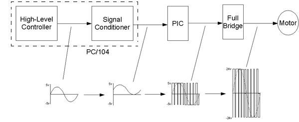
This motor controller was designed for use as cheap, simple motor controller for [[Brushed DC Motor Theory|brushed DC motors]]. It uses a [[PIC Microcontroller]] to convert a low-power analog control signal to a [[Pulse Width Modulation|PWM]] duty cycle which is amplified using a full-bridge to drive a motor. A block diagram of this is shown below. This document gives the circuitry and programming needed to make such a controller. |
This motor controller was designed for use as cheap, simple motor controller for [[Brushed DC Motor Theory|brushed DC motors]]. It uses a [[PIC Microcontroller]] to convert a low-power analog control signal to a [[Pulse Width Modulation|PWM]] duty cycle which is amplified using a full-bridge to drive a motor. A block diagram of this is shown below. This document gives the circuitry and programming needed to make such a controller. |
||
| Line 43: | Line 45: | ||
[[image:PWM PIC Input Conditioner.png|center]] |
[[image:PWM PIC Input Conditioner.png|center]] |
||
[[image:PWM PIC Input Circuit.jpg|400px|center]] |
|||
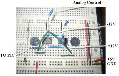
This circuit can accomodate inputs of either <math>\pm\,</math>5V or <math>\pm\,</math>10V. The two potentiometers can be adjusted to give the correct gain. Diodes were added to protect the PIC from too low or too high voltage inputs. |
This circuit can accomodate inputs of either <math>\pm\,</math>5V or <math>\pm\,</math>10V. The two potentiometers can be adjusted to give the correct gain. Diodes were added to protect the PIC from too low or too high voltage inputs. |
||
| Line 48: | Line 52: | ||
Another way around this is to add an enabling input. Whenever the controller isn't running, the circuit can be disabled so the motors won't be accidentally driven in either direction. |
Another way around this is to add an enabling input. Whenever the controller isn't running, the circuit can be disabled so the motors won't be accidentally driven in either direction. |
||
== |
==PCB Example== |
||
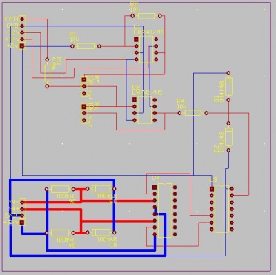
You can download CircuitMaker and TraxMaker files here for this circuit using the L293. The PCB design is shown below. It is not optimized for space, but to be easy to read. You can edit it as you like. It is suited to use with the PC/104 stack. |
|||
* [[media:PIC PWM Circuit Files.zip]] |
|||
[[image:PIC PWM Traxmaker.jpg|center|400px]] |
|||
==TO DO== |
==TO DO== |
||
# Find out why circuit causes motors to make high-pitch noise. |
|||
# Add "brake" functionality to the PIC. This will require at least one additional input. For example, a single digital input pin could cause the motor to "brake" when it's set high. To "brake", the PIC will have to disable the PWM mode and set the two output pins equal to eachother. |
# Add "brake" functionality to the PIC. This will require at least one additional input. For example, a single digital input pin could cause the motor to "brake" when it's set high. To "brake", the PIC will have to disable the PWM mode and set the two output pins equal to eachother. |
||
# Add "sensing" capability for better control. |
# Add "sensing" capability for better control. |
||
Latest revision as of 12:25, 10 February 2009
Overview
DO NOT USE THIS PAGE. USE THE OTHER PWM PAGE.
This motor controller was designed for use as cheap, simple motor controller for brushed DC motors. It uses a PIC Microcontroller to convert a low-power analog control signal to a PWM duty cycle which is amplified using a full-bridge to drive a motor. A block diagram of this is shown below. This document gives the circuitry and programming needed to make such a controller.
PIC PWM
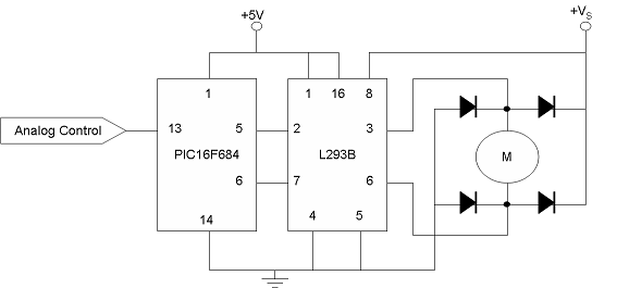
The first thing you need is a PIC microcontroller set up to convert an analog input to a PWM signal. The PIC used here is the PIC16F684. It only has one input, the analog control signal. It has two outputs: two opposite pulse width modulated pulse trains. The two PWM signals activate the two halves of the H-bridge to control the direction of the motor.
PIC Code
Code can be downloaded here.
The zip file contains the following files:
- main.asm - the program
- macros.inc - contains macros (quick code)
- PIC16F684.INC - assigns names to register addresses
- PICPWM.mcw and PICPWM.mcp - MPLAB workspaces
Circuit
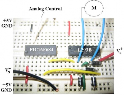
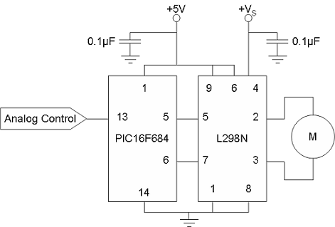
The circuit consists of the PWM-enabled PIC chip, an amplifier and some protection circuitry. There are two versions of the circuit, one for low-power motors (1A continuous) and one for high-power motors (4A continuous).
Low Power
The low-power circuit uses the L293B push-pull driver (datasheet). This circuit can be used for the 6W Maxon motors in the lab.
High Power
A more high-power circuit makes use of the L298N (datasheet) full bridge amplifier.
Signal Conditioner (Optional)
There is a problem with leaving out the signal conditioner part of the circuit. Sure you can program your controller to output your control signal scaled to 0 to +5v, but when it will likely reset to 0v at some point. 0v to the PIC corresponds to full speed in one direction. You want 0v to the circuit to mean 0 speed to the motor, or 0v (IN) = 2.5v (PIC). For this you can build a simple op-amp circuit.
This circuit can accomodate inputs of either 5V or 10V. The two potentiometers can be adjusted to give the correct gain. Diodes were added to protect the PIC from too low or too high voltage inputs.
Another way around this is to add an enabling input. Whenever the controller isn't running, the circuit can be disabled so the motors won't be accidentally driven in either direction.
PCB Example
You can download CircuitMaker and TraxMaker files here for this circuit using the L293. The PCB design is shown below. It is not optimized for space, but to be easy to read. You can edit it as you like. It is suited to use with the PC/104 stack.
TO DO
- Find out why circuit causes motors to make high-pitch noise.
- Add "brake" functionality to the PIC. This will require at least one additional input. For example, a single digital input pin could cause the motor to "brake" when it's set high. To "brake", the PIC will have to disable the PWM mode and set the two output pins equal to eachother.
- Add "sensing" capability for better control.
