Programmable Stiffness Joint
Team Members
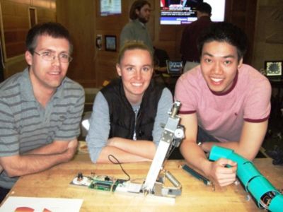
- Amanda Care (Senior in Mechanical Engineering, Northwestern University)
- Eric Nickel (Graduate Student in Biomedical Engineering, Northwestern University, BS in Biomedical Engineering from the Milwaukee School of Engineering)
- James Yeung (Junior in Electrical Engineering, Northwestern University)
Overview
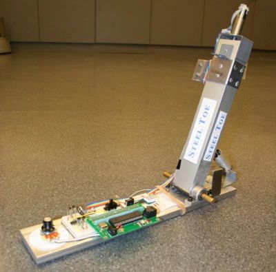
The "Programmable Stiffness Joint" is a device which is able to internally modify the rotational stiffness of a simple pivot joint. It is intended to serve as a proof-of-concept for future work in developing a model for determining the respective damping and stiffness components of the human ankle joint over the able-bodied gait cycle. This information in turn will permit prosthetists and rehabilitation engineers to design and fit prostheses better designed for the user's gait kinetics, which in turn should produce more natural gait kinematics.
The goal of our project is: To develop a working model of a device which is able to control the stiffness of a joint in such a manner as to mimic the motion of a human ankle joint. The user is able to select a stiffness level and the device will adjust itself to provide the specified level of rotational stiffness. The set-point of the joint will remain constant for all stiffnesses.
This is how it works: A linear coil extension spring has a constant stiffness within its elastic extension limit. As the location of the insertions of the spring on the base and rotating member change position, the amount of spring extension experienced for a given angular change of the rotating member will vary, as will the torque produced by the spring tension. These variations are taken advantage of to produce widely different stiffnesses from a single linear extension coil spring.
We will discuss:
- Stiffness theory and the conceptual framework which guided the design of the device
- Mechanical design and function of the device
- Electrical design and function of the device
- PIC control and the software developed to control the device
- Results of final testing
- Future work and lessons learned
Stiffness Theory
The rotational stiffness of a joint is defined as the torque required to cause a given angular rotation.
Fundamental Equation
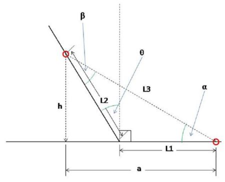
Based upon the diagram at right, the following variables are defined for these equations:
- L1 = The distance from the pivot point to the "heel" insertion point of the linear spring on the base plate
- L2 = The distance from the pivot point to the "shank" insertion point of the linear spring on the rotating element
- L3 = The distance between the two insertion points
- h = The height of the insertion point on the rotating member for a given angle and L2
- a = The horizontal component of the position of the insertion point location on the rotating member for a given angle and L2
- theta = The angle of the rotating member with respect to the vertical (perpendicular to the base plate)
- beta = The angle of the spring tension with respect to the rotating member
Below is the bottom line for rotational stiffness. For more detailed information, see the separate Rotational Stiffness page.
There are three major aspects to consider for rotational stiffness:
First, a linear spring requires a constant incremental force to achieve a given incremental change in the spring length. This is described by Hook's Law (shown below) where F is the force applied to the spring, x is the change in length of the spring (in this case, it will only be extension), and k is the stiffness of the linear spring.
Due to this relationship, the amount of extension of the spring will determine the tension force applied to the sliding insertion point on the rotating member. Therefore as the amount of spring extension increases, the amount of rotational stiffness increases.
Secondly, a torque (T) is the result of a force (F) applied at a distance (d) from the axis of rotation. As the distance from the axis increases, the torque produced by a given tension force increases, therefore the rotational stiffness increases.
Lastly, the angle (beta) between the tension force and the rotating member matters. Only the component of the force which is tangential to the rotation is generating torque. The rest of the force becomes a compressive force in the rotating member, and does not contribute. As the angle between the spring and the vertical member decreases, the rotational stiffness decreases.
This all condenses into the following torque formula in terms of the variables from the conceptual diagram:
T = k * ( (L2*cos(theta))^2 + (L1+L2*sin(theta))^2 )^1/2 * sin(beta) * L2
MATLAB Simulation
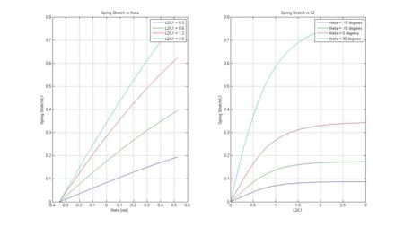
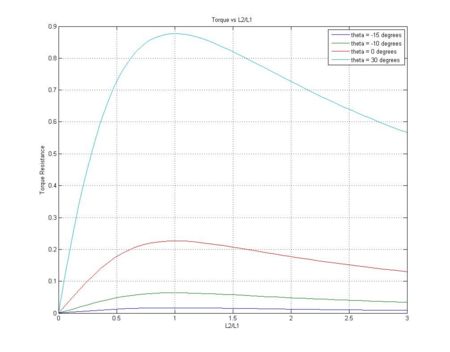
Simulations of the above theory in MATLAB produced the following results.
Over the range of motion of this device (-20 degrees to +30 degrees) the spring stretch is pretty close to linear. This suggests that there will be limited change of joint rotational stiffness due to non-linear spring stretch.
As the L2/L1 ratio increases, there seems to be a plateau for L2/L1 > 2. This suggests that the torque gain due to spring tension in this region would be minimal.
The peak torque produced by the spring seems to be at a ratio of L2/L1 = 1. Above this point, the angle beta is too small, and not enough of the spring tension force is tangential to the rotation, so the torque actually decreases. Below this ratio, the amount of spring stretch is decreasing, resulting in reduced torque. The ideal region to be working within is the region:
MATLAB Code
The matlab code used to produce the plots used in this section and the Rotational Stiffness page is linked below.
The code is heavily commented and is intended to be used either stand-alone or in conjunction with the Rotational Stiffness page. The plots produced are internally formatted and ready for viewing upon running the code. The code computes and plots the location of the sliding insertion point on the rotating member relative to the stationary insertion point on the base. It also computes and plots the amount of spring stretch experienced for a given combination of rotation and insertion distance ratios, assuming that the spring is given slack so that the neutral angle is consistent at -20 degrees (or -pi/9 radians). Finally, it computes the amount of tension force actually being used to produce torque as well as the respective moment arm, and from that plots the amount of torque required to achieve the rotation at different insertion distance ratios.
True rotational stiffness would be the incremental change in torque needed to produce a small change in angle, however the code does not perform this computation. From the plots, over the range of angles used for this application the torque vs angle curves are close to linear, and therefore we assumed a linear relationship for the sake of simplicity and ignored the differential stiffness. If the joint were to incorporate a larger range of motion or were to be required to maintain a specific stiffness, computing the actual stiffnesses over the range of angles and insertion distance ratios would be necessary, however this project did not require that.
Mechanical Design
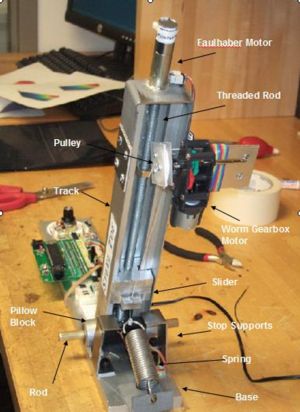
The Mechanical Design consists of six main parts, the base, track/slider, threaded rod, spring, and two motors. The track, base, and spring are representative of the three main parts of an ankle joint: the foot, leg, and calf muscle respectively. We have specified 10 different stiffness levels based on the height of the slider. The slider sits on the threaded rod and moves up and down the track as the motor spins the rod to adjust its position. One motor is used to turn the rod, which controls the height of the slider. The other motor is used to tighten the spring after the height of the slider has been set.
Structural Components
- Base - The base is connected to the track by the pillow blocks and rod. It is also connected to the spring. In the ankle joint, the base would be equivalent to the foot. The base is made out of aluminum.
- Track - The track is connected to the base through the use of pillow blocks and a rod. The track allows the slider to stay in place and be moved to different heights based on the desired stiffness. The track is an extruded part made out of aluminum alloy.
- Spring - Depending on the position of the slider, the spring extends different amounts for the same rotation, thus providing different rotational stiffness to the joint. The spring is connected to a cable, allowing it to maintain unstretched at the set point for different slider heights.
- Slider - The slider sits in the track and has a tapped hole down the middle allowing the threaded rod to sit inside it. It is moved up and down the track depending on the way the threaded rod spins. It also has another hole allowing the cable to pass through and connect to the spring. The position of the slider determines the force the spring applies to the system. The slider is a milled piece of aluminum.
- Threaded Rod - The threaded rod sits inside the slider and causes the slider to change heights depending on the direction of rotation. The threaded rod is rotated by the Faulhaber Motor. It is a 3/8 inch threaded rod.
- Faulhaber Motor w/ Encoder - The Faulhaber motor is connected to the threaded rod by a set screw. As the motor turns, so does the rod. The encoder keeps track of the number of rotations, allowing us to control the position of the slider.
- Pillow Blocks - The pillow blocks elevate the track enough to allow it to rotate freely.
- Rod - The rod is made of brass. It connects the track to the pillow blocks and allows rotation of the joint.
- Pulley and Cable - The pulley is driven by a motor with a worm gearbox to prevent back driving. The cable goes through a hole in the slider and connects to the spring.
- Tamiya Worm Gearbox Motor - The gearbox motor controls the pulley and cable and serves to tighten the spring once the slider is in the appropriate height.
- Stop Supports - The stop supports serve as a resting point for the track when the spring is not in tension or when the slider is in the lowest position.
How It Works
Once a change in the desired stiffness is detected, the Worm Gearbox Motor turns the pulley to provide a little slack to the cable. Then the Faulhaber motor would spin the rod in the direction that will move the slider to the desired position that corresponds to the desired stiffness. Once the slider gets to the desired position, the Worm Gearbox Motor turns the pulley until all slack in the cable has been removed. Now, the new desired stiffness level has been set.
Electrical Design
Component List
| Part | Part No. (Spec Sheet) | Qty | Vendor (Where to Buy) | Unit Price |
|---|---|---|---|---|
| Microchip 8-bit PIC Microcontroller | PIC18F4520 | 1 | Microchip | ~$4.50 |
| Faulhaber Motor w/ Encoder | 1524E006S123 | 1 | Electronic Goldmine | $7.95 |
| Tamiya Worm Gearbox High Efficiency Kit | TAM72004 | 1 | Hobbylinc | $9.09 |
| H-Bridge Chip | L293B | 1 | Digi-Key | $4.32 |
| Diodes | 1N4001RLOSCT-ND | 8 | Digi-Key | $0.23 |
| 7-Segment Display | LTD-4708JS | 1 | Digi-Key | $1.20 |
| 7-Segment Display Chip | HEF4543B | 1 | Digi-Key | $0.50 |
| 100K Pot Linear Taper w/ Dial | Jameco 29102 | 1 | Discontinued | N/A |
| Lever/Limit Switch | SW152-ND | 1 | Digi-Key | $1.10 |
| Slider Switch | Jameco 135378 (Variety Pack) | 1 | Jameco | ~$0.14 |
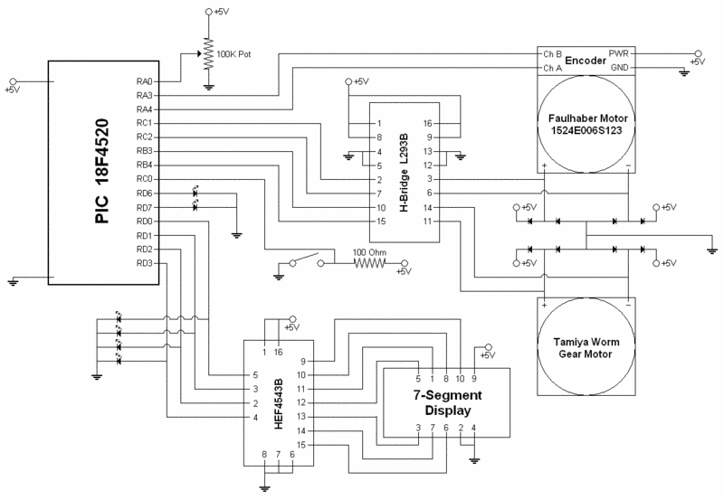
Circuit Diagram
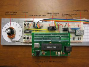
Here's a detailed drawing of the circuit. The interface with the PIC microcontroller has been ignored but more information about how to put one together is available here.
Code
Overview Comments
/*////////////////////////////////////////////////////////////////////////////////////////////////////////////
stiffness_control.c, j.yeung, a.care, e.nickel 2008-01-31

This code is to be used with the programmable stiffness joint.

OVERVIEW
A reset routine is run when the program starts that will run the Fauhaber motor until the slider hits the
switch.  The reset routine will then reset the encoder count to 0.  Then the program polls the analog input
to see what stiffness level the knob is turned to.  If the desired stiffness level is different from the
current stiffness level, the program will move the slider to the desired level.  The program also controls
the worm drive motor passively as the slider moves to ensure that there is enough slack for the slider to
move and also to tighten up the slack after the slider has reached its position.

NOTES
RD0 - binary output for 7-segment display
RD1 - binary output for 7-segment display
RD2 - binary output for 7-segment display
RD3 - binary output for 7-segment display
RD6 - digital output for encoder miscounts
RD7 - digital output for calibration button
RC0 - digital input for calibration button
RC1 - digital output for PWM of rod motor (low = down, high = up)
RC2 - CCP1 output for PWM of rod motor
RB3 - CCP2 output for PWM of cable motor
RB4 - digital output for PWM of cable motor (low = in, high = out)
RA0 - analog input from dial
RA3 - channel B input from rod motor encoder
RA4 - channel A input from rod motor encoder
/////////////////////////////////////////////////////////////////////////////////////////////////////////////*/
PIC Initialization
//PIC Initialization///////////////////////////
#include <18f4520.h>                         // command to include the header for the PIC.
#DEVICE ADC=10                               // set ADC (analog input) to 10 bit accuracy
#fuses HS, NOLVP, NOWDT, NOPROTECT, CCP2B3   // some standard fuses, CCP2B3 moves CCP2 to output at RB3
#use delay(clock=20000000)                   // 20 MHz crystal on PCB
///////////////////////////////////////////////
Encoder Control
//Encoder Control//////////////////////////////
signed int32 encoder_count=0;                // it is signed so just in case it goes negative, it doesn't overflow.
int8 encoder_state=0;                        // will contain only 4 relevant bits: A & B state last time, and this time
                                             //
signed int decoder_lookup[16] = {0, -1, +1, 0, +1, 0, 0, -1, -1, 0, 0, +1, 0, +1, -1, 0};
signed int32 target[10] = {100, 2750, 5500, 8250, 11000, 13750, 16500, 19250, 22000, 24650};
                                             // decoder_lookup is to determine which way the motor is going
                                             // target is to determine what is the target encoder count for each stiffness level.
                                             //
#INT_TIMER2                                  // designates that this is the routine to call when timer2 overflows
void Timer2isr() {                           // see ServoSkeleton for how this ISR can interrupt others
                                             //
   encoder_state = ((((encoder_state << 1) + input(PIN_A4)) << 1) + input(PIN_A3)) & 15;
                                             // shift over the old states and record the new states
                                             //
   encoder_count += decoder_lookup[encoder_state];
                                             // use decoder_lookup table to determine motor direction and update encoder_count
                                             //
   if ( ((encoder_state & 8) >> 3) != ((encoder_state & 2) >> 1)
         && ((encoder_state & 4) >> 2) != ((encoder_state & 1) >> 0)) {
      output_high(PIN_D6);                   // turn on D6 LED if there is a miscount
   }                                         //
   else{                                     //
      output_low(PIN_D6);                    // turn off D6 LED if there is no miscount
   }                                         //
}                                            //
///////////////////////////////////////////////
Reset Routine
//Reset Routine////////////////////////////////
void reset(){                                // only called at the beginning of program
   int i=8;                                  //
   int j=0;                                  //
                                             //
   output_low(PIN_C1);                       // set rod motor direction to down
   set_pwm1_duty(78);                        //
   output_high(PIN_B4);                      // set cable motor direction to reel-out
   set_pwm2_duty(0);                         //
   delay_ms(150);                            // let cable motor reel-out for 150ms
   output_low(PIN_B4);                       // stop cable motor
                                             //
   while(input(PIN_C0) == 1){                // keep moving the slider down until the limit switch is closed
      if (i==8){                             // for every 4 seconds
         output_high(PIN_B4);                // let cable motor reel-out for 75ms
         if(j>40){                           // if rod motor has been running for more than 20 seconds
            delay_ms(50);                    // only let cable motor reel-out for 50ms
         }                                   //
         else{                               //
            delay_ms(75);                    //
         }                                   //
         output_low(PIN_B4);                 //
         i=0;                                //
      }                                      //
      delay_ms(500);                         //
      i++;                                   //
      j++;                                   //
   }                                         //
                                             //
   set_pwm1_duty(0);                         // stop rod motor
   output_low(PIN_B4);                       // set cable motor direction to reel-in
   set_pwm2_duty(78);                        // reel-in for 1500ms
   delay_ms(1500);                           //
   set_pwm2_duty(0);                         // stop cable motor
   encoder_count = 50;                       // reset encoder counter
   delay_ms(1000);                           // wait for 1 second
}                                            //
///////////////////////////////////////////////
Change Stiffness
//Change Stiffness/////////////////////////////
signed int8 level_old=0;                     // these are signed to allow for math operations in the function
signed int8 level_new=0;                     //
                                             //
void change_stiffness(){                     // only called when there's a change in desired stiffness level
   int i=0;                                  //
                                             //
   if(level_new - level_old < 0){            // if desired level is lower than previous level
      output_high(PIN_B4);                   // set cable motor direction to reel-out
      set_pwm2_duty(0);                      // reel-out for 500ms
      delay_ms(500);                         //
      set_pwm2_duty(78);                     // stop cable motor
                                             //
      while(encoder_count > target[level_new]){
                                             // until the encoder count reaches the new desired count
         if(i == 100){                       // for every 5 seconds
            output_high(PIN_B4);             // set cable motor direction to reel-out
            set_pwm2_duty(0);                // reel-out for 50ms
            delay_ms(50);                    //
            set_pwm2_duty(78);               // stop cable motor
            i = 0;                           //
         }                                   //
         output_low(PIN_C1);                 // set rod motor direction to down
         set_pwm1_duty(78);                  // run rod motor
         delay_ms(50);                       //
         i++;                                //
      }                                      //
      set_pwm1_duty(0);                      // stop rod motor after target has been reached
   }                                         //
                                             //
   else{                                     // desired level is higher than previous level
      output_high(PIN_B4);                   // set cable motor direction to reel-out
      set_pwm2_duty(0);                      // reel-out for 100ms
      delay_ms(100);                         //
      set_pwm2_duty(78);                     // stop cable motor
                                             //
      while(encoder_count < target[level_new]){
                                             // until the encoder count reaches the new desired count
         if(i == 100){                       // for every 5 seconds
            output_low(PIN_B4);              // set cable motor direction to reel-in
            set_pwm2_duty(78);               // reel-in for 50 ms
            delay_ms(50);                    //
            set_pwm2_duty(0);                // stop cable motor
            i = 0;                           //
         }                                   //
         output_high(PIN_C1);                // set rod motor direction to up
         set_pwm1_duty(0);                   // run rod motor
         delay_ms(50);                       //
         i++;                                //
      }                                      //
      set_pwm1_duty(78);                     // stop rod motor after target has been reached
   }                                         //
                                             // after desired level is reached, tighten slack
   output_low(PIN_B4);                       // set cable motor direction to reel-in
   set_pwm2_duty(78);                        // reel-in for 1500ms
   delay_ms(1500);                           //
   set_pwm2_duty(0);                         // stop cable motor
}                                            //
///////////////////////////////////////////////
Vref Update
//Vref_update//////////////////////////////////
int16 Vref_old=0;                            // need 16 bit because we chose 10 bit accuracy
int16 Vref_new=0;                            //
                                             //
void Vref_update(){                          // routine to update dial/display and call change_stiffness()
   Vref_new = read_adc();                    // update dial value
                                             //
   if (abs(Vref_new - Vref_old) > 30){       // software schmitt trigger
      if (Vref_new < 1023){                  //
         level_new = 0;                      //
      }                                      //
      if (Vref_new < 918){                   //
         level_new = 1;                      //
      }                                      //
      if (Vref_new < 816){                   //
         level_new = 2;                      //
      }                                      //
      if (Vref_new < 714){                   //
         level_new = 3;                      //
      }                                      //
      if (Vref_new < 612){                   //
         level_new = 4;                      //
      }                                      //
      if (Vref_new < 510){                   //
         level_new = 5;                      //
      }                                      //
      if (Vref_new < 408){                   //
         level_new = 6;                      //
      }                                      //
      if (Vref_new < 306){                   //
         level_new = 7;                      //
      }                                      //
      if (Vref_new < 204){                   //
         level_new = 8;                      //
      }                                      //
      if (Vref_new < 102){                   //
         level_new = 9;                      //
      }                                      //
      output_d(level_new);                   // update value on 7-segment display
      if(level_new != level_old){            //
         change_stiffness();                 // change stiffness to new desired level
         level_old = level_new;              // update level_old
         Vref_old = Vref_new;                // update Vref_old
      }                                      //
   }                                         //
}                                            //
///////////////////////////////////////////////
Main Function
//MAIN/////////////////////////////////////////
void main(){                                 //
                                             //
   setup_timer_2(T2_DIV_BY_4, 77, 16);       // 16KHz clock, interrupt every 4*50nS * 4 * (77+1) * 16 = 1.0mS
                                             // third argument means the clock is running 16x faster than the interrupt routine, if any
   enable_interrupts(INT_TIMER2);            // initialization for ISR
   enable_interrupts(GLOBAL);                //
                                             //
   setup_ccp1(CCP_PWM);                      // PWM output on CCP1/RC2, pin 17
   setup_ccp2(CCP_PWM);                      // PWM output on CCP2/RB3, pin 36.
                                             //
   output_high(PIN_C1);                      // initialize rod motor
   set_pwm1_duty(78);                        //
                                             //
   output_high(PIN_B4);                      // initialize cable motor
   set_pwm2_duty(78);                        //
                                             //
   setup_adc_ports(AN0);                     // Enable analog inputs; choices run from just AN0, up to AN0_TO_AN11
   setup_adc(ADC_CLOCK_INTERNAL);            // the range selected has to start with AN0
                                             //
   set_adc_channel(0);                       // there's only one ADC so select which input to connect to it; here pin AN0
   delay_us(10);                             // wait 10uS for ADC to settle to a newly selected input
   Vref_old = read_adc();                    // now you can read ADC as frequently as you like
                                             //
   reset();                                  // run the reset routine
                                             //
   while (TRUE) {                            //
      Vref_update();                         // update the dial
      if(input(PIN_C0) == 1){                // turns on D7 LED if the limit switch is pressed, only for visual reference
         output_high(PIN_D7);                //
      }                                      //
      else{                                  //
         output_low(PIN_D7);                 //
      }                                      //
      delay_ms(100);                         //
   }                                         //
}                                            //
///////////////////////////////////////////////
Results and Reflections
Overall Results
Overall, our project was a great success. There were things that could have been done differently and can be improved, but we managed to achieve what we have set out to do, which was to make a device that models a joint and have the ability to change its rotational stiffness. We hope that "Steel Toe" will aid researchers in creating better prosthetic legs and joints for people in need.
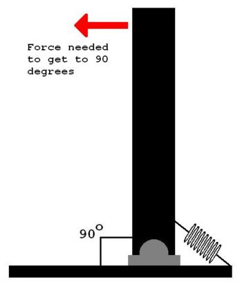
In terms of obtaining some quantitative results, by testing to see how much horizontal force was needed to pull the shank to 90 degrees, we found that "Steel Toe" was able to achieve a factor of about 5 in the range of stiffnesses. Here's a table of our test results.
| Stiffness Level | Force Needed to Get to 90 Degrees |
|---|---|
| 0 | 2.943 N |
| 1 | 3.434 N |
| 2 | 4.415 N |
| 3 | 5.886 N |
| 4 | 7.358 N |
| 5 | 9.810 N |
| 6 | 11.282 N |
| 7 | 12.263 N |
| 8 | 13.734 N |
| 9 | 14.715 N |
Possible Mechanical Improvements
- Move circuitry to shank.
- Reduce weight of foot plate.
- Use faster motor for spinning the rod (or gear up current motor) to increase adjustment speed.
Possible Electrical/Software Improvements
- Have the program continuously check for changes in dial. Currently it is only checking when motors are not moving.
- Use a different H-bridge chip to replace existing diodes. L293D instead of L293B.
Future Directions
The actual stiffness of the joint is not constant over the range of motion. For this limited range of motion, a linear approximation is valid, however more precise computations accounting for the non-linearity could be of use.
This device could be modified in design to incorporate more powerful motors to drive the slider faster and even possibly during loading to achieve a stiffness which can change during the gait cycle to adapt to conditions or simply better conform to natural gait kinetics.
Following this device with a model incorporating programmable damping would be another step toward differentiating between the elastic stiffness and damping properties of the ankle joint during walking.
