4520 Board construction
Assembling the 4520 board
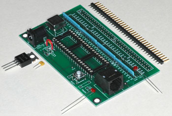
Shown is the smaller half of the 4520 PCB, with most of the parts laid out in proper orientation for assembly.
The larger half of the 4520 PCB is the same, but with a "solderboard" area attached as well.
Note:
- The regulator chip can be replaced by a jumper (red wire in the photo) if you are using a 5.0V regulated power supply
- The anode (positive) side of an LED is usually the longer lead. + and - are marked on the PCB
- A vertical-insertion 6-6 modular jack can also be used; just cut off the plastic tabs.
- A 20MHz oscillator is soldered directly to the board, bu the PIC18F4520 chip is socketed.
- The marked pin (dot) on the 9-pin SIPs is the common bus for all eight 1K resistors inside. The proper insertion for the SIP is indicated by a dot on the PCB. The SIPs go in with altenating orientation (two each way).
- Ceramic capacitors are non-polarized and can be intalled either way. Use two if you use a regulator (1uF preferably). One or two without a regulator.
- The resistor near the reset switch is 4.7K (or whatever) and the resistor near the LED is 1K (or whatever).
- The 36-pin SIP header is intended to insert into a solderless breadboard. It's under the PCB, with the longer gold-plated pins downward.
Getting a DIP-40 into its socket
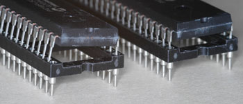
The 40-pin PIC 18F4520 chip has legs a bit too wide to fit the socket. They're designed to be squashed during automated insertion. You can't do that, and if you try you will wind up buckling the legs. Instead, bend a row of legs (all 20 on one side) by pressing the side of the row of legs against a hard tabletop and tipping the chip up until the legs stay perpendicular to the chip body. Do this on both sides. Now it will fit the socket. Get all the legs into their holes, and press down firmly into the socket with two thumbs. Should you need to remove it without destroying it, work it out from underneath with a flat-bladed screwdriver.
Barrel plug conventions
As noted in the intro, you can use a regulator or not, depending if you are planning to use a >5V power supply which needs regulating down to 5.0V, or if you are planning to use an already-well-regulated 5.0V supply.
We are trying to stick to a convention of using a 5.5mm/2.5mm barrel plug & jack for 5.0V exactly, and a 5.5/2.1mm barrel plug & jack for >5V.
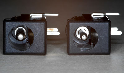
It's difficult to distinguish these connectors visually, but you'll find that the 2.1 plug won't fit into the 2.5 jack, thus preventing the more unfortunate error. (2.5mm and 2.1mm refer to the diameter of the pin inside.)
You can distinguish the jacks by looking straight inside. In the photo, the 2.5mm is on the left, and the 2.1mm on the right. Note the wider annular collar around the smaller 2.1mm pin.


