USB Communication Board
***Under Construction***
Overview
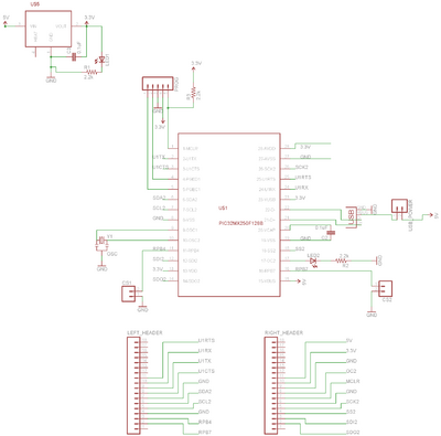
The NU USB Communication Board is a universal communication board which serves as an interface between PCs and embedded systems. Using a PIC32MX250 chip, the board translates between USB HID communication and low-level microcontroller communication protocols, including RS232, I2C, and SPI. This board is useful in circumstances when fast, reliable communication is desired between a microcontroller and PC, but resources are not available on the microcontroller to run a full USB stack. The schematic and images of the copper traces are shown below.
Using the USB Communication Board
The USB protocol used on this board operates in the HID class. This is beneficial because no drivers are required for any operating system, and low latency is guaranteed. The USB in operation on this board delivers 64 byte packets every millisecond in both directions. For this reason, all streaming data coming from the embedded side will be "packetized" by the board into 63 byte packets, using the first byte as a descriptor.
Micro-controller Side
The board operates in one of four modes: RS232, RS232 with Hardware Flow Control, SPI, or I2C. This mode is selected upon board power-up by the CommSelect jumpers on board. The selection criteria are shown below
- No Jumpers - RS232
- CS1 Jumped - RS232 w/ Hardware Flow Control
- CS2 Jumped - SPI
- Both Jumped - I2C
RS232
In RS232 mode, the communication board will read in any characters over the RS232 U1RX line and send them in 63 byte packets to the computer via USB. The zeroth byte of the USB 64-byte packet describes the length (N) of the data packet being sent to the computer, and has a maximum value of 63. Bytes 1 through N are filled with the pertinent data being sent to the computer. Bytes N+1 through 63 are meaningless. Each one of these packets is sent out every millisecond, for a maximum throughput of 63 kB/s.
Any packets received from the computer will be fed out the U1TX line. Again, the zeroth byte of the packet from the computer should contain the number of relevant bytes, as to not bog down the U1TX line with meaningless data.
RS232 w/ Hardware Flow Control
This mode operates under the same principle, but uses the U1RTS and U1CTS lines for flow control. This allows for higher baud-rates, and possibly higher-speed communication.
SPI
In development
I2C
In development
PC Side
Processing
To send and receive USB packets in Processing on the computer, we use a Java Native Interface library which uses C libraries to communicate via USB. We have included the library in an example processing sketch for you, but if you're interested in using the Java library for something else, documentation and downloads for this library can be found here. This is the template Processing sketch which simply listens for characters and prints them out in the text pane, and sends them back to the device. The code directory contains the .jar file containing the Java library. These files need to be here, but do not require editing.
In the sketch itself, the USBListener file defines a Thread which listens to the USB port. The function pic.read() will wait until the USB buffer is not empty, and then place the first-in data into the specified variable. This thread is also a good place to update all state variables and send out data to the PIC using pic.write(). The HIDManager file contains the code to connect and set up the USB communication with the PIC device. The NU USB Communication Board has product ID: 0, so the proper function call to open the pic is openPic(0);
Here is the API documentation, which explains what each function does.
Matlab
In development
Source Code
9/4/2012 - Source Project


