Audio recording and playback
Original Assignment
Using the ISD1110 voice chip, and a speaker and microphone provided to you, demonstrate a circuit that allows you to record and play back sounds. Demonstrate it under PIC control. See if you can record and play back multiple sounds, as chosen by the PIC.
Overview
The ISD1100 voice chip is a single chip solution which allows for both the recording and playback of a 10 second audio clip, either in its entirety or in small pieces. Using only an electret microphone, a speaker and minimal circuitry a simple system can be developed.
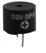
Our circuit used a 16 Ohm mini-tone transducer and a typical electret microphone with two wire leads.
An electret microphone is easy to use with the chip. For more information on electret microphone theory and operation visit the microphones page. A 16 ohm speaker is recommended for use with the ISD1110.
The chip can be run under PIC control. Using the code below, a user can start the recording process, enable the playback and even address specific locations of the recording by using the RS-232 connection to the PIC.
Both recording and playback are enabled by connecting the corresponding pin on the chip to ground or digital low. A specific portion of the recording is accessed by sending an address to the ISD1110 chip. The recording can be accessed at increments of 125 milliseconds.
There have been some issues with amplification to an easily audible level. If this is the case an external audio amplifier may be necessary to achieve the desired results.
Circuit
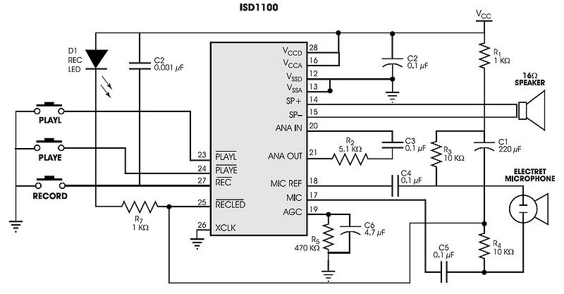
The circuit to the right shows the suggested configuration of the ISD1110 chip, as shown in the chip data sheet.
When using the PIC to control the chip, the push buttons can be removed. The PLAYL, PLAYE and REC pins (pins 23, 24 and 27) should be connected to a digital output from the pic. In the code provided, these three pins correspond to outputs CO, C1 and C2 respectively. Also, to utilize the addressing capabilities of the chip, pins 1-6, 9-10 (labeled A0-A7 on the ISD1110) need to be connected to pins D0-D7 on the PIC.
When testing the circuit, the desired voltage level at the microphone input is approximately 20 mV peak-to-peak, and the voltage across the speaker pins should be roughly 1.25V.
As mentioned above, if the desired amplification is not achieved with this circuit, an external audio amplifier may be necessary between the speaker output pins and the speaker itself.
Adjusting the values of the components in the circuit may help to remove noise from the signal and get a better signal quality, however, the values given are as specified in the data sheet for normal operation.
Parts
Electret Microphone - x1

16 Ohm Speaker - x1

ISD1110 - x1

LED - x1

1 kOhm Resistor - x2

5.1 kOhm Resistor - x1

10 kOhm Resistor - x2

470 kOhm Resostor - x1

0.001 uF Capacitor - x1

0.1 uF Capacitor - x4

4.7 uF Capacitor - x1

220 uF Capacitor - x1
Code
The code below should be programmed onto the PIC, and operated using the RS-232 connection.
The code basically takes one of four input commands and changes the 11 digital output pins (PLAYL, PLAYE, REC and A0-A7) to implement the desired command on the ISD1110 chip. For example, holding the REC pin low starts and continues the recording process until the output goes high, or all of the recording time is used up. Each of the commands can be implemented with an address ('a') and a duration ('d'). An address is an integer 0-80 which selects a specific 125 millisecond interval to start at, and a duration is given in milliseconds. The commands are as follows:
rec a d; This will start recording at an address 'a' and record for a duration 'd'
NOTE: The end of recording marker will be placed at the end of this recording and any information stored at a later time will be lost.
play a; This will play a recording at an address 'a'
loop d; This will continuously play the recording for a duration 'd'
chunk a d; This will play a recording starting at an address 'a' and last for a duration 'd'
Here are some examples:
rec; Records for the entire 10 seconds starting at the beginning.
rec 40 2000; Records for 2 seconds starting at 5 seconds.
NOTE: The end of recording marker is placed at 7 seconds, and seconds 7-10 are inaccessible.
play 40; Plays the recording starting at 5 seconds.
loop 40000; Loops the entire recording for 40 seconds.
chunk 40 30000; Plays the portion of the recording from 5 seconds to 8 seconds.
#include <18f4520.h>
#include <string.h>
#include <stdlib.h>

#fuses HS,NOLVP,NOWDT,NOPROTECT
#use delay(clock=40000000)
#use rs232(baud=9600, UART1)

// hardware setup
#define HIGH 1
#define LOW 0
#define REC_PIN PIN_C2
#define PLE_PIN PIN_C1
#define PLL_PIN PIN_C0

// software setup
#define BUFFER 100
#define IS_CMD(i, c) (!stricmp((i), (c)))
#define ENTER 0x0D
#define DUR_PER_MEM_LOC 125 // ms
#define MAX_MEM_LOC 80
#define MAX_DURATION 10000 // ms
#define BASE 10
#define PULSE_ENABLE 10 // ms
#define LOOP_ENABLE 0b11001000 // A7, A6, & A3 on (see ISD1100 data sheet)

char REC_CMD[] = "rec";
char PLAY_CMD[] = "play";
char LOOP_CMD[] = "loop";
char CHUNK_CMD[] = "chunk";

/**
* activates the play pin with a level signal
*/
void play_l(int8 a, int16 d)
{
  printf("<<>> you sent a play segment @ %u for %lu command\r\n", a, d);
  output_d(a);
  output_bit(PLL_PIN, LOW);
  delay_ms(d);
  output_bit(PLL_PIN, HIGH);
  output_d(LOW);
}

/**
* activates the looping feature
*/
void loop(int16 d)
{
  printf("<<>> you sent a loop @ %u for %lu command\r\n", a, d);
  output_d(LOOP_ENABLE);
  output_bit(PLE_PIN, LOW);
  output_bit(PLE_PIN, HIGH);
  delay_ms(d);
  output_bit(PLL_PIN, LOW);
  output_bit(PLL_PIN, HIGH);
  output_d(LOW);
}

/**
* activates the play pin with pulse signal
*/
void play_e(int8 a)
{
  printf("<<>> you sent a play @ %u command\r\n", a);
  output_d(a);
  output_bit(PLE_PIN, LOW);
  delay_ms(PULSE_ENABLE);
  output_bit(PLE_PIN, HIGH);
  output_d(LOW);
}

/**
* activates the record pin with a level signal
*/
void record(int8 a, int16 d)
{
  printf("<<>> you sent a record @ %u for %lu command\r\n", a, d);
  output_d(a);
  output_bit(REC_PIN, LOW);
  delay_ms(d);
  output_bit(REC_PIN, HIGH);
  output_d(LOW);
}

/**
* parses a command from an RS-232 prompt
*/
void run_cmd(char *input)
{
  int16 addr, dur;
  char *delim = " ;";
  char *cmd;

  cmd = strtok(input, delim);
  addr = strtoul(strtok(NULL, delim), NULL, BASE);
  dur = strtoul(strtok(NULL, delim), NULL, BASE);

  if(!dur) {
     dur = MAX_DURATION;
  }

  if(addr > MAX_MEM_LOC) {
     printf("<<>> oops address is out of range (0 <= addr <= %u).\r\n",
        MAX_MEM_LOC);
  }
  else if(IS_CMD(cmd, REC_CMD)) {
     record(addr, dur);
  }
  else if(IS_CMD(cmd, PLAY_CMD)) {
     play_e(addr);
  }
  else if(IS_CMD(cmd, LOOP_CMD)) {
     loop(dur);
  }
  else if(IS_CMD(cmd, CHUNK_CMD)) {
     play_l(addr, dur);
  }
  else {
     printf("<<>> oops invalid command \"%s\", try again!\r\n", cmd);
  }
}

/**
* event loop
*/
void main(void)
{
  int i;
  char input[BUFFER + 1]; // need to make space for the null character

  output_d(LOW);
  output_bit(REC_PIN, HIGH);
  output_bit(PLE_PIN, HIGH);
  output_bit(PLL_PIN, HIGH);

  while(TRUE) {
     // reset parameters
     i = 0;
     memset(input, '\0', sizeof(input));

     // gather input
     while(i < BUFFER && (input[i] = getc()) != ENTER) {
        putc(input[i]);
        i++;
     }
     printf("\r\n");

     // check input
     if(i == BUFFER) {
        printf("<<>> ERROR: your input is too long\r\n");
     }
     else {
        run_cmd(input);
     }
  }
}

