Difference between revisions of "Optoreflector"
m (→Application) |
m (→Application) |
||
| Line 17: | Line 17: | ||
|} |
|} |
||
There are two ways to process the output. 1) build extra circuitry using a schmidtt trigger or 555 timer to turn the output into a digital output. 2) Use an analog input and use a software threshold. The second way is easier and |
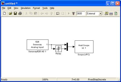
There are two ways to process the output. 1) build extra circuitry using a schmidtt trigger or 555 timer to turn the output into a digital output. 2) Use an analog input and use a software threshold. The second way is easier and works well. Start with the program below to adjust your voltage thresholds (using the relay block) and light sensitivity (by adjusting the potentiometer). |
||
[[image:qrb1114 xpc program.jpg|center]] |
[[image:qrb1114 xpc program.jpg|center]] |
||
Revision as of 13:00, 10 August 2006
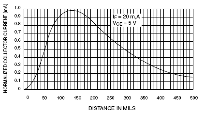
Optoreflector sensors contain a matched infrared transmitter (LED) and infrared receiver (usually a phototransistor) pair. These devices work by measuring the amount of light that is reflected into the receiver. Because the receiver also responds to ambient light, the device works best when well shielded from abient light, and when the distance between the sensor and the reflective surface is small (the graph below shows how distance affects the output value). IR reflectance sensors are often used to detect white and black surfaces. White surfaces generally reflect well, while black surfaces reflect poorly.
Application
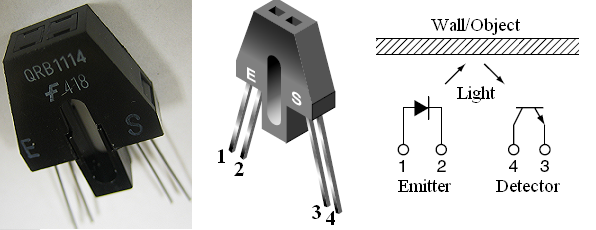
In the mechatronics lab, we have the QRB1114 (datasheet) from Fairchild, shown below. It has four pins, with the first pair connected to the LED and the second pair connected to the phototransistor.
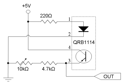
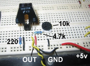
The circuit below can be used to detect objects directly in front of the QRB1114. The potentiometer must be used to adjust for ambient lighting conditions. The output is an analog signal like the one at the top of the page - dependent on distance.
There are two ways to process the output. 1) build extra circuitry using a schmidtt trigger or 555 timer to turn the output into a digital output. 2) Use an analog input and use a software threshold. The second way is easier and works well. Start with the program below to adjust your voltage thresholds (using the relay block) and light sensitivity (by adjusting the potentiometer).
