Difference between revisions of "XBee Interface Board"
From Mech
Jump to navigationJump to search| Line 28: | Line 28: | ||
====2mm Socket==== |
====2mm Socket==== |
||
Make sure the sockets go in straight. If they are crooked, the XBee radio will not be able to plug in. |
Make sure the sockets go in straight. If they are crooked, the XBee radio will not be able to plug in. |
||
[[Image:xbee_interface_socket_wrong.jpg| |
[[Image:xbee_interface_socket_wrong.jpg|320px|left]] [[Image:xbee_interface_socket_right.jpg|320px|left]] |
||
Revision as of 00:01, 5 April 2008
The pins on the XBee radio (Digikey XB24-AWI-001-ND) have a pitch of 2 mm, which makes it impossible to plug into a standard 0.1 inch pitch breadboard. The XBee Interface Board allows one to plug the XBee into a breadboard or directly into a FTDI USB-RS232 cable.
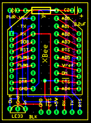
Board Schematic
Assembling the Board
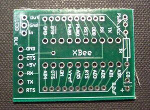
PCB
This is the PCB. If the PCB has fibers sticking out of the edge, scrape or file them off. These are glass fibers, and can stick into your finger like a splinter.
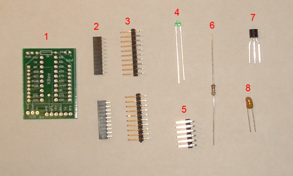
Components
Not all of the components are required. The voltage regulator and capacitor go together; if you don't need the regulator, you won't need the capacitor either.
- PCB
- 2x 10 pos. 2 mm pitch socket (Digikey S5751-10-ND)
- 2x 10 pos. header pin (broken off Digikey S1011E-36-ND)
- low current LED (Digikey 160-1086-ND)
- 6 pos. 90 degree header pin (broken off Digikey S1111E-36-ND)
- 1k resistor
- LE-33 low dropout voltage regulator (Digikey 497-4258-1-ND)
- 2.2uF tantalum capacitor (Digikey 399-3536-ND)
Populating the Board
2mm Socket
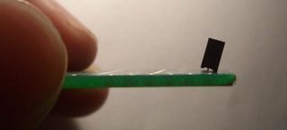
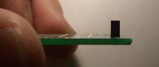
Make sure the sockets go in straight. If they are crooked, the XBee radio will not be able to plug in.
