Three-speaker Chladni Patterns
Team Members
- Christopher Chow (Mechanical Engineering, Class of 2010)
- Anup Tapase (Electrical Engineering, Class of 2010)
- Lingyu Xie (Electrical Engineering, Class of 2009)
Overview
The purpose of this project was to build on the past projects that have been seen on Youtube and other sites involving vibrating a metal plate using one speaker or violin bow. This project uses three speakers separated by 120 degrees which vibrate a circular plate to generate patterns with salt. These patterns are created because when the speakers hit the resonant frequency of the plate, nodes are created on the plate and the salt migrates to these nodes because they are vibrating the least. The project should also include a user interface which the user can use to select different patterns or frequencies for the plate.
Theory
Equations
As explained in the overview, the Chladni plate generates patterns when the frequency of the plate oscillation is at a resonant frequency for the plate. At resonance, the plate has portions where it has non-zero amplitude during oscillation, which is where the salt moves away from toward areas of zero amplitude. Areas of zero amplitude are called nodes or zeros of vibration, and salt collects at these regions on the plate at resonance. The nodes of vibration of a circular or square plate can be mathematically calculated for different modes of vibration.
The equation solves for the zeros of the standing wave for a square plate constrained at the center, such as the one we used for our one-speaker configuration. The variable L is the side length of the plate, m is the number of diametric nodes and n is the number of radial nodes. Solve for x and y for the zero locations.
The equation to find the zeros for a circular plate is . The Jn(K*r) term is using the n-th order Bessel function.
The following equation is Chladni's Law: . This equations relates the modes of vibration to the frequency of the modes for circular plates with a fixed center, similar to the one used by our three-speaker system except that our plate is fixed at three points away from the center. In the equation, C and p are defined based on the properties of the plate. For circular plates, p is approximately 2. The values of m and n are chosen based on the diametric and radial modes which can be determined by the shape of the salt on the plate, then converted to the frequency of the plate that made that shape.
Mechanical Design
The Chladni pattern generator setup is pretty straightforward. There were three major areas of design we had to account for. One was how to adapt the speakers to attach to the metal plate, the second was the speaker housing, and the third was the user interface/circuit box. These are detailed with pictures below.
If you are trying to replicate this project, note that many of these specifications can change and still yield interesting, but different results. Another thing to note is all the specifications are for our particular speakers. Dimensions and materials can change according to what you're working with and what is available.
Parts List
The parts and prices below are specific to the project we did. You can change many of the parts to suit different components. We were fortunate to have most of the materials in supply so we could save money for the aluminum plate and electronics.
| Part | Part No. | Qty | Vendor | Price (Total) |
|---|---|---|---|---|
| PYRAMID 8" Originals 300W | WX85 | 3 | Lab | - |
| AL 6061) .032" THICK, 36"X36" | 89015K71 | 1 | McMaster | $53.23 |
| Wood stock | - | ~40"X40" | Shop supply | - |
| Polystyrene Sheets | - | ~20"X40" | Shop supply | - |
| PVC tube 1.5" Dia | - | ~ 1 ft | Shop supply | - |
| Polycarbonate sheet | - | ~6"X6" | Shop supply | - |
| Nuts, Bolts, Washers | - | ~20 | Shop supply | - |
| Foamcore | - | 2 Sheets 36"X28" | EDC Supply | - |
| L Brackets | - | ~20 | Shop supply | - |
Breakdown of Components
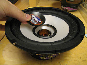
Adapting Speakers
> First we cut away the dust-cap as pictured to the right
> Glued onto the diaphragm of the speaker and over the dustcap is a 2 inch long PVC pipe that covers the hole.
> Over the PVC pipe we glued a 2" x 2" piece of polycarbonate.
> We screwed a hole into the center of the polycarbonate and put in a screw.
The screw is fastened with nuts and washers. The flexible aluminum plate will ultimately be attached to the speaker through this screw.
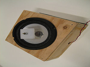
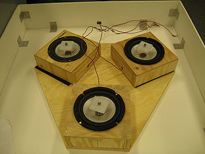
Speaker-boxes and Base
> Cut a hole into the top of the speaker box to seat the speaker.
> We planned the base so that the speakers would be radially separated by 120 degrees and the centers of each speaker to create a 13" equilateral triangle with each other.
> We lined the bottoms of the speaker boxes and the base with Velcro for convenience and accessibility.
> The speaker set up sits in a 32" x 32" foamcore box reinforced with L-brackets. This is to catch the salt that spills off of the aluminum plate.


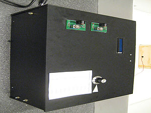
User Interface and Circuit Box
> A simple box with a hinged top that can be made out of anything, we chose to use a black Polystyrene material that was available.
> The user interface panel needs to have slots cut for the two power switches, and LCD screen, and a knob. The laser printer and mill were both used to make these cutouts.

Putting it Together
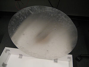
> The last piece needed is a metal plate. We cut down the 36" x 36" aluminum plate into a 28" diameter circular plate.
> Pictured to the side is the complete set up.
Electrical Design
Primary Components
The primary components required to implement the circuit include:
1) PIC 18F4520
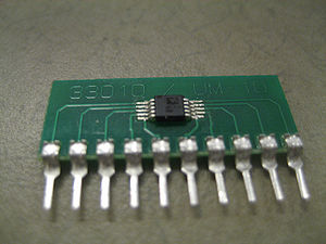
2) AD9833 BRMZ-ND Function Generator chip *
3) LM 741 Op Amp (x3)
4) JHD 162A Parallel LCD
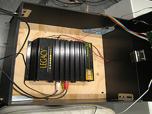
5) Car audio amplifier, at least 3-channel (Legacy LA160 4 Channel 300 Watt used here)
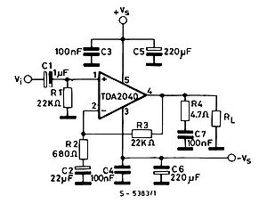
Alternative components that are needed if car amplifier is not available:
1) TDA 2040 audio amplifier chip
*Note: The AD9833 is a surface mount chip, and needs a 10-pin adaptor, 33010CA-ND onto which it is soldered. A picture of this is shown on the right.
Circuit Notes
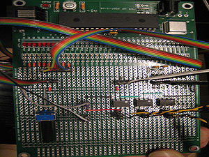

The PIC communicates with the AD9833 function generator chip through SPI interface. Refer to Waveform Generation with AD9833, and SPI for how to use this chip. The Master Clock is connected to the CLK of the PIC, and the three SPI communication lines are connected to the three I/O pins A1, A2 and A3 on the PIC. Through the code described below via SPI, information about the wave to be generated is transmitted and the function wave is generated accordingly.
A 10K potentiometer is used as input from the user in the form of a knob to set the frequency. It is connected to pin A0 of the PIC, and its use is described in detail under the Code section.
The output of the AD9833 chip is connected to the non-inverting inputs of three LM741 Op Amps. These op-amps are not used to amplify the signal, but to serve as a unity gain buffer for the signals. They are connected to a +/- 12V power supply. This buffer essentially makes a copy of the input at the output, without drawing any current from the source of the input, i.e., the function generator chip, which gets its power from the PIC supply. Instead, the output signal draws power from the op-amp itself. The goal is to ensure that doing the measurement of a voltage does not disturb the circuit producing the voltage to be measured.
The outputs of the op-amps are then connected to the car amplifier using standard RCA input cables. The car amplifier, which is connected to a 12V supply, amplifies the signal to audible amplitudes and the outputs are connected to the three speakers. The speakers draw power from the car amplifier.
The D0-D6 outputs of the PIC are connected to the Parallel LCD. To learn more about how to get the LCD working, refer to C Example: Parallel Interfacing with LCDs. The LCD is made to display the target frequency that the user inputs using the knob (which is on the potentiometer), and also the value of the frequency of the wave that is being generated at the moment.
For easier and more convenient use, sockets were made for header pins from the power supplies, potentiometer, RCA input cables and the parallel LCD. This way, the components can be plugged in and out easily.
Circuit Diagram

NEED TO INCLUDE STUFF ABOUT
- WARNING ABOUT HOW DELICATE THE AD9833 CHIP IS
- USE OF MORE THAN ONE AD9833
- AUDIO AMP CIRCUITS
Code
Main frequency sweep code
The first thing that this code does is that it initializes the variables target_freq_reg and old_target_freq_reg to the register value of 298 Hz, which is a non-resonant frequency. See Waveform_Generation_with_AD9833,_and_SPI to find out how to convert between frequency and register value for commands sent to the AD9833 function generator chip, and sending commands to the AD9833 using SPI. After this, the analog port pin is set up and the lcd_init() function is called to set up the LCD display. The LCD displays the current frequency that the AD9833 is currently outputting and the target frequency that the chip is supposed to sweep up/down to. See C Example: Parallel Interfacing with LCDs to learn about how to interface and send information to the LCD.
Once the initial set up information is finished, the code sends the first frequency command to the AD9833, starting it at a frequency of 298 Hz by giving it the target_freq_reg register value (initialized at 298 Hz). This allows the speakers to sweep up to the first resonant frequency and oscillate the salt into the first resonant shape when the system is turned on. The register values are then converted to Hz and displayed on the LCD. From there, the code goes into a while() loop which continuously checks the input from the user interface knob which indicates the target frequency that the AD9833 should go to. After getting the target frequency from check_input(), the code compares this new frequency information to the old frequency information (old_freq_reg). If they are different, then the knob was switched to a new frequency and the AD9833 needs to sweep up or down to the new frequency. Depending on whether the new frequency is above or below the old frequency, a for-loop will keep sending new frequency register commands to the AD9833, shifting up or down by 1 Hz every 100 ms, constantly updating the LCD to display the current and target frequency, until the actual frequency is equal to the target frequency. The function check_input() is called for each iteration of the for-loop to check if the target frequency was changed. The old_target_freq_reg is then set equal to the target_freq_reg and the program then holds at this one resonant frequency until the knob sends a different target_freq_reg.
/*
Chladni Code
Lingyu Xie, Anup Tapase, Chris Chow
ME333 Winter 2009
*/
#include <18f4520.h>
#DEVICE ADC=8                   // set ADC to 8 bit accuracy
#use delay(clock=40000000)
#include "flex_lcd.c"             //must include in order to output to LCD
#use spi(DO = PIN_A3, CLK = PIN_A2, ENABLE = PIN_A1, BITS = 16, MASTER, ENABLE_ACTIVE = 0, MSB_FIRST, IDLE = 1)

int16 freq,target_freq;
int16 target_freq_reg, old_target_freq_reg;
int8 knob_val=0;

void check_input();

void main()
{
   int16 ct;

   target_freq_reg=2000+16384;         // initialize starting frequency of speakers to 298 Hz (non-resonant)
   old_target_freq_reg=2000+16384;     // set old target freq variable to equal target freq

   setup_adc_ports(AN0);               // Set up analog input port as pin A0
   setup_adc(ADC_CLOCK_INTERNAL);

   lcd_init();  // Always call this first.

   //INITIAL FREQUENCY FOR AD9833
   spi_xfer(0b0010000100000000); //format command, output sine wave

   spi_xfer(target_freq_reg);    //1st set of bits, 14 LSB, this range is good enough for our use
                                 //send the target frequency register value (freq + 16384) to AD9833 chip
   spi_xfer(0b0100000000000000); //2nd set of bits, 14 MSB

   spi_xfer(0b1100000000000000); //phase register: 0 phase shift (B0-B13)

   spi_xfer(0b0000000000000000); //unformat

   freq=(float).149011 * (float)(target_freq_reg - 16384);  //convert the target freq register value to actual freq value
   target_freq=freq; // initialize target freq as current freq

   printf(lcd_putc,"\fFreq: %Lu Hz\n",freq); //display current freq
   printf(lcd_putc,"Target: %Lu H\n",target_freq); //display target freq

   while(TRUE)
   {
      check_input(); //check the knob input to see if target frequency has changed

      if(old_target_freq_reg != target_freq_reg) //go in here if target freq changed after calling check_input()
      {
         if(target_freq_reg > old_target_freq_reg) //sweep up to target freq
         {
            for(ct=old_target_freq_reg; ct<=target_freq_reg; ct=ct+7) //ct+7 approximate increases frequency by 1 Hz
            {
               spi_xfer(0b0010000100000000);

               spi_xfer(ct); //set AD9833 frequency to ct, which is freq register that is sweeping up by 7 each time loop is run
               spi_xfer(0b0100000000000000);

               spi_xfer(0b1100000000000000);

               spi_xfer(0b0000000000000000);

               freq=(float).149011 * (float)(ct - 16384);
               target_freq=(float).149011 * (float)(target_freq_reg - 16384);

               printf(lcd_putc,"\fFreq: %Lu Hz\n",freq); //display current freq
               printf(lcd_putc,"Target: %Lu Hz\n",target_freq); //display target freq

               check_input(); //see if knob position has selected different target freq
               delay_ms(90);  //delay to allow speakers to play freq for 90 ms + 10 ms (in check_input() function)
            }

            old_target_freq_reg = target_freq_reg; //reached target freq, set both variables equal until knob position changed

         }
         else if(target_freq_reg < old_target_freq_reg) //sweep down to target freq
         {
            for(ct=old_target_freq_reg; ct>=target_freq_reg; ct=ct-7) //ct+7 approximate decreases frequency by 1 Hz
            {
               spi_xfer(0b0010000100000000);

               spi_xfer(ct); //set AD9833 frequency to ct, which is freq register that is sweeping down by 7 each time loop is run
               spi_xfer(0b0100000000000000);

               spi_xfer(0b1100000000000000);

               spi_xfer(0b0000000000000000);


               freq=(float).149011 * (float)(ct - 16384); //convert current freq register value (ct) to frequency value
               target_freq=(float).149011 * (float)(target_freq_reg - 16384); //convert target freq register to target freq value

               printf(lcd_putc,"\fFreq: %Lu Hz\n",freq); //display current freq
               printf(lcd_putc,"Target: %Lu Hz\n",target_freq); //display target freq

               check_input(); //see if knob position has selected different target freq
               delay_ms(90);  //delay to allow speakers to play freq for 90 ms + 10 ms (in check_input() function)
            }

            old_target_freq_reg = target_freq_reg; //reached target freq, set both variables equal until knob position changed
         }
      }
   }
}
Checking user input
This function is used to check the knob/potentiometer position at certain points during the changing of frequencies in the main function. It sets the ADC channel to 0 and takes the analog input from pin A0 on the PIC using read_adc(). This input, set to the variable knob_val, is an integer between 0-255 which corresponds to the voltage coming out of the knob/potentiometer, which is 0 if the output is at 0V and 255 if the output is at 5V. By checking if knob_val is between a certain integer range corresponding to the different numbers on the knob (numbered 0-10), the target frequency can be set by the user. Nine target resonant frequencies were programmed in this function based on the good clarity of the shapes they produced on the plate, but more resonant frequencies exist and can be added to the if-statement in this function. The target frequency registers should be adjusted depending on the plate shape and size.
void check_input() //check knob position to see if target freq has changed
{
      set_adc_channel(0);     // Set the analog input channel to 0
      delay_us(10);           // wait 10uS for ADC to settle to a newly selected input
      knob_val = read_adc();  // Read in knob user input to tell speakers what resonant freq to sweep up to

      delay_ms(10);           // delay 10 ms to allow reading of analog input

      //check and set target_freq_reg according to knob position (0-255 values split into 9 discrete levels)
      if (knob_val >= 0 && knob_val< 22 )
         target_freq_reg = 2281+16384; //339 Hz
      else if(knob_val >= 22 && knob_val< 54)
         target_freq_reg = 3308+16384; //493 Hz
      else if(knob_val >= 54 && knob_val< 86)
         target_freq_reg = 3778+16384; //563 Hz
      else if(knob_val >= 86 && knob_val< 117)
         target_freq_reg = 3986+16384; //594 Hz
      else if(knob_val >= 117 && knob_val< 147)
         target_freq_reg = 4207+16384; //627 Hz
      else if(knob_val >= 147 && knob_val< 178)
         target_freq_reg = 4362+16384; //650 Hz
      else if(knob_val >= 178 && knob_val< 209)
         target_freq_reg = 5006+16384; //746 Hz
      else if(knob_val >= 209 && knob_val< 239)
         target_freq_reg = 5308+16384; //791 Hz
      else if(knob_val >= 239 && knob_val< 255)
         target_freq_reg = 5872+16384; //875 Hz
}
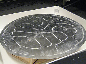
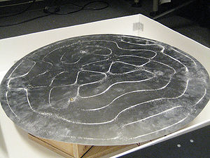
Results
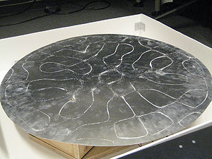
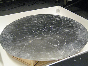
Three-Speaker Chladni
The following images show the results of the Three-Speaker Chladni system at six different resonant frequencies. Some of these frequencies have clearer patterns than others, such as 424 Hz, 554 Hz, and 660 Hz. The less-clear ones might be due to imperfections in the plate or the speakers not hitting the exact resonant frequency. Some frequencies shown in these results are different than the ones in the code displayed above. The ones displayed below were chosen for their clarity and contrast from each other because some frequencies in the displayed code do not shift in pattern as much.
Click here for a video of our Three-speaker Chladni setup

Three-Speaker Configuration at 339 Hz
424 Hz
554 Hz

632 Hz
660 Hz
734 Hz
One-Speaker Chladni
Click here for a video of our one-speaker Chladni setup
As you can see from the previous video, the one-speaker setup gives more distinct patterns than our three-speaker setup. This may be because there is no other interference with the vibration that more speakers connected to the same plate may cause. The patterns are all very different from each other, indicating the different diametric and radial modes of the square plate.
Experimental Notes
AD9833 Waveform Generator
While a tremendously versatile and useful chip, we found it extremely difficult to work with. The chip itself is very small and as mentioned above needs to be soldered to an adapter. Surface mount soldering this chip is not easy to do by hand and the connection may be weak even if you've tested with a multimeter. We even found that performance of the chip can be improved simply by putting pressure on the chip which shows how difficult making a solid connection can be. However if working properly this chip can be very powerful.
SPI communication with multiple AD9833 chips
Possible Future Improvements/Enhancements
-Try sending different frequencies (by figuring out how to program multiple AD9833 chips) to each speaker to see if they generate different patterns
-Use different plate size or add 4th speaker and use large square plate to change the types of visible shapes at resonance
-Figure out issue with TDA-2040 audio amp so the project wouldn't have to rely on car audio amp
-Use more rigid plate or construct one with less defects in shape
References
Chladni Plate Mathematics
Chladni's Law
A study of vibrating plates