Test
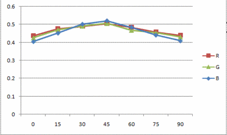
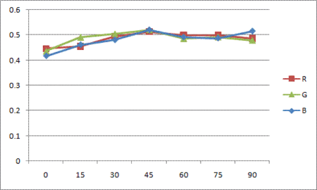
LED Angle vs Color Sensor Signal
The second experiment is designed to see how much interference will be caused as the angle between LED and color sensor changes. Different from the first experiment, Vi, the voltage before amplified, is mesured since amplified output, Vo, easily reaches to the maximum.
Setup and Results
1. A white LED is used again in this experiment with the same reason above for the first experiment.
- LED: 18950 mcd, Digikey part number: C503B-WAN-CABBB151-ND
2. The experiment was performed under the two conditions; with the ambient light and without the ambient light.
3. In this experiment, the distance between LED and color sensor is kept constant, 1 inch.
4. Angle between LED and color sensor is increased by 15º each time from 0º to 90º.
When the angle is 0º, the LED and the color sensor is placed at the same horizontal plane. The LED is facing toward the color sensor(this means that the LED is parallel to the horizontal plane with its head facing the color sensor, which is placed on the same horizontal plane), and the color sensor is facing upward. We increased the angle by 15º each time, and increasing amounts of light from the LED shines onto the color sensor. When the angle is 90º, the LED is right above the color sensor, facing the color sensor directly. This means that the LED and the color sensor are now on the same vertical line, and the LED is facing downward.
5. The voltage before amplified, Vi as shown in the circuit diagram above, of each photodiode is measured.
- The reason to measure the volatage before amplified is that the output becomes too large after amplified.
With the Ambient Light
- Unit: Volt, V
| Angle | R | G | B |
|---|---|---|---|
| 0º | 0.437 | 0.425 | 0.404 |
| 15º | 0.475 | 0.470 | 0.451 |
| 30º | 0.490 | 0.491 | 0.501 |
| 45º | 0.505 | 0.506 | 0.520 |
| 60º | 0.484 | 0.468 | 0.484 |
| 75º | 0.457 | 0.453 | 0.440 |
| 90º | 0.439 | 0.430 | 0.408 |
Without the Ambient Light
- Unit: Volt, V
| Angle | R | G | B |
|---|---|---|---|
| 0º | 0.446 | 0.436 | 0.416 |
| 15º | 0.454 | 0.491 | 0.461 |
| 30º | 0.493 | 0.505 | 0.480 |
| 45º | 0.512 | 0.521 | 0.520 |
| 60º | 0.498 | 0.486 | 0.491 |
| 75º | 0.498 | 0.492 | 0.487 |
| 90º | 0.485 | 0.479 | 0.515 |
As the first experiment, two graph above shows that the color sensor is affected by the light from the LED. The color sensor is most affectd by the LED when the angle between two is 45º. The inteference increases as the angle goes to 45º, and reaches to the peak at 45º. Then it decreases as the angle goes to 90º. When the color sensor is most affected by the LED under the presence of the room light, the output increases upto 15.6%, 19.1%, and 28.7% of Vi. As angle becomes 90º, the output becomes very close to the value at the angle of 0º. The reason why the interference is reduced as the angle reaches 90º is that the ambient light presented are blocked by the LED board. When we perform this experiment, the LEDs are implemented on the LED plane. This LED plane blocks the light and make a shadow on the color sensor. Thus, the amount of light that the color sensor receives decreases. That is why the output becomes close to its original value while the angle increases.

