Stepper Motor Circuits
Basics
To control a stepper motor, you have to energize each winding individually in a specific and timed order. The energizing is accomplished by a driver circuit (an amplifier). The timing is performed by an indexer circuit and the objective (go forward, go backward, brake, coast, etc.) is controlled by some external user interface, such as a computer or joystick. The figure below shows this process.
Indexing
Drivers
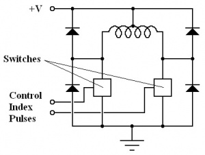
The circuits for driving unipolar and bipolar stepper motors differ because bipolar stepper motors don't have a "center tap." However, it is possible to use bipolar drivers to drive unipolar steppers after some small modifications.
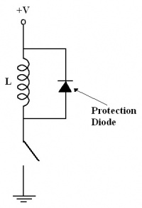
Care must be taken in the driver circuit to protect against voltage spikes. Because the motor windings are inductors, switching off the power to the winding produces a short burst of voltage. To protect against this, always put a diode in parallel with the winding, making sure the diode can handle the winding current. This is shown in the following figure.
Unipolar Stepper Driver Circuit
The basic drive circuitry for a single unipolar winding is shown in the following figure.
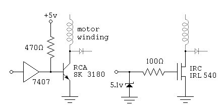
For the switches, any kind of switching technology can be used. The following figure shows two such switches. The first one uses a power darlington transistor and the second one uses a power field effect transistor.
Bipolar Stepper Driver Circuit
References
- "Stepper Motor Basics", http://www.ams2000.com/pdf/step101.pdf
- "Jones on Stepping Motor Control Circuits", http://www.cs.uiowa.edu/~jones/step/circuits.html


