Unused files
From Mech
Jump to navigationJump to searchThe following files exist but are not embedded in any page. Please note that other web sites may link to a file with a direct URL, and so may still be listed here despite being in active use.
Showing below up to 250 results in range #101 to #350.
View (previous 250 | next 250) (20 | 50 | 100 | 250 | 500)
 Dc motor speed torque curve.png 598 × 450; 50 KB
 Lab1-2006.pdf ; 1.39 MB
 Lab1-2006.doc ; 830 KB
- Lab2-2006.pdf ; 105 KB
- Lab2-2006.doc ; 55 KB
- Lab3-2006.pdf ; 121 KB
- Lab3-2006.doc ; 57 KB
- Lab4-2006.pdf ; 303 KB
- Lab4-2006.doc ; 143 KB
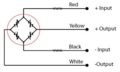
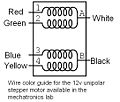 Stepper wire colors.jpg 541 × 458; 42 KB
- Optoreflector analog.zip ; 13 KB
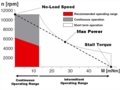
 Maxon-characteristics.gif 539 × 483; 83 KB
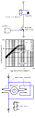
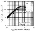 Mosfetgraph.jpg 400 × 364; 38 KB
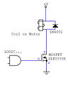 Mosfetcircuit.jpg 300 × 375; 11 KB
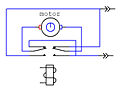 Reversingrelay.jpg 380 × 287; 14 KB
 Mosfet2.jpg 300 × 1,015; 52 KB
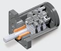 Gear spurgearhead.jpg 281 × 240; 15 KB
- ULQ2003A.pdf ; 508 KB
 PWM-low-duty-cycle-small.jpg 614 × 461; 67 KB
 PWM-high-duty-cycle-small.jpg 614 × 461; 60 KB
 PWM-signals-small.jpg 614 × 461; 59 KB
 H-bridge-outs-small.jpg 614 × 461; 67 KB
 Stampsnap.jpg 824 × 868; 88 KB
 Unstack.jpg 400 × 326; 40 KB
 Stampsnap2.jpg 834 × 878; 110 KB
 Debugmenu.jpg 206 × 46; 14 KB
 DACckt.jpg 360 × 279; 23 KB
 Digitalinckt.jpg 350 × 294; 29 KB
 4520boardtopwiki.jpg 600 × 403; 127 KB
- Puck-gettingstarted.pdf ; 855 KB
- Tutorial.zip ; 20 KB
- E-puck-snapshot.tar.gz ; 843 KB
- EpuckMonitor.zip ; 378 KB
 Pwm3.gif 1,045 × 832; 27 KB
 4520board ckt.gif 443 × 428; 17 KB
 4520-big.jpg 1,000 × 665; 165 KB
 4520-lines.jpg 1,000 × 671; 307 KB
 Pinsbroughtout.gif 600 × 381; 48 KB
 Pinsbroughtout.jpg 600 × 381; 63 KB
 Max232n-01.gif 400 × 256; 12 KB
 Max232n-02.gif 417 × 513; 18 KB
 Usb-serial-adapter.jpg 280 × 280; 5 KB
 Max232n-05.gif 450 × 513; 19 KB
 Pwm2.gif 384 × 260; 3 KB
- Color filters.pdf ; 187 KB
 I2C Data Transfer.svg ; 12 KB
- Stepper.zip ; 5 KB
 Stepper.c ; 5 KB
- StepperMotor.c ; 5 KB
- StepperM.c ; 5 KB
- Circuit.tif 2,550 × 3,300; 285 KB
 Example.jpg 885 × 476; 138 KB
 7SegmentCircuit.JPG 600 × 450; 32 KB
 7SegmentCitcuit3.JPG 600 × 450; 34 KB
 7SegmentCircuit2.JPG 571 × 600; 17 KB
 4708JS Pic1.JPG 600 × 568; 18 KB
 4708JS Pic2.JPG 571 × 600; 19 KB
 7SegmentCircuit3.jpg 600 × 450; 34 KB
 4708JS Pic1.jpg 598 × 510; 75 KB
 SerialCom.jpg 635 × 472; 880 KB
 Copper clad board.jpg 2,551 × 1,209; 394 KB
 Microphone circuit.JPG 881 × 600; 54 KB
 Wiki img circuit mic.JPG 881 × 600; 54 KB
- Stepper control.c ; 3 KB
 Mic circuit diagram.JPG 512 × 384; 14 KB
 Mic circuit diagram2.JPG 512 × 384; 14 KB
 PIC18f4520 spi diagram.jpg 417 × 217; 14 KB
 PIC18f4520 spi diagram 417 × 217; 14 KB
 PIC18f4520 spi diagram 2.jpg 417 × 217; 14 KB
 Serial ir data format.jpg 733 × 471; 34 KB
 Pic2xbee.gif 1,024 × 768; 35 KB
 Fig1.gif 500 × 251; 7 KB
 Spi-circuit.jpg 448 × 251; 107 KB
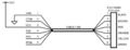 Usb-rs232-cable-pinout.jpg 600 × 232; 29 KB
- Vendor-request.pdf ; 119 KB
 IR Tracker.jpg 753 × 594; 37 KB
 Temp.jpg 753 × 594; 3 KB
 HPIM1027.JPG 648 × 488; 123 KB
 Team Members.jpg 640 × 480; 100 KB
 CVT setup1.jpg.jpg 800 × 533; 94 KB
 CVT setup1.jpg 800 × 533; 94 KB
 CVT limit switches.jpg 800 × 533; 46 KB
 CVT control circuit.jpg 880 × 660; 104 KB
 SteelToePic.jpg 807 × 691; 113 KB
- IR Tracker.c ; 11 KB
- Wiimouse.m ; 9 KB
- Wiimouse.fig ; 1 KB
- Wiimouse.c ; 2 KB
 Snake Robot.jpg 512 × 384; 45 KB
 Snake Robot Intro.jpg 512 × 384; 45 KB
- Baseball final.c ; 7 KB
- Iterative Learning Control 423 × 854; 282 KB
 LearningOscMC.jpg 876 × 657; 170 KB
 LearningOscAM.jpg 876 × 657; 72 KB
 Baseball array explanation.jpg 867 × 526; 54 KB
- SteelToeCode.c ; 15 KB
 ProgStiffJointConcept.jpg 960 × 720; 31 KB
 Baseball Sensor.jpg 1,052 × 900; 150 KB
 Smlearningoscillationcircuit 1,024 × 719; 41 KB
 Mechanical Design Labels.bmp 189 × 252; 140 KB
 Image-Mechanical Design Labels.bmp 189 × 252; 140 KB
 Coinslot.JPG 2,816 × 2,112; 2.33 MB
- BKSBallSlave1v1.c ; 8 KB
- Reimbursement.pdf ; 58 KB
- Reimbursement.xls ; 17 KB
- Tumbler.zip ; 937 KB
 Circuit 2.GIF 256 × 203; 2 KB
- TrackSysTraining 6 20 08.zip ; 2.06 MB
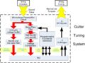
 GTTP System.jpg 1,932 × 1,720; 625 KB
 GTTP system.jpg 1,375 × 1,019; 362 KB
 GTPP Headset.JPG 410 × 309; 25 KB
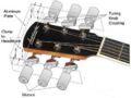 GTTP Headset.JPG 410 × 309; 25 KB
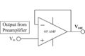 GTTP Voltage Buffer.jpg 451 × 301; 28 KB
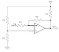 Hysteresiscomparatorcircuit.JPG 481 × 428; 21 KB
- Error creating thumbnail: File missingAD9833Conn.jpg 343 × 345; 22 KB
 Lateral effect psd.gif 742 × 610; 18 KB
- PCBArtist.jpg 1,227 × 757; 161 KB
 Selectboard.jpg 396 × 246; 38 KB
 DropComp.jpg 611 × 339; 25 KB
 Netweb.jpg 621 × 312; 57 KB
 Routedcircuit.jpg 589 × 477; 63 KB
 AccelXYwiki.jpg 496 × 478; 50 KB
 AccelXZwiki.JPG 536 × 510; 57 KB
 AccelYZwiki.JPG 521 × 483; 52 KB
 Schematic of phase sensitive detection.jpg 949 × 669; 78 KB
 FX1901 Diagram.jpg 376 × 227; 11 KB
- Hbridge v4.pcb ; 74 KB
- Epuck xbee board v2.PCB ; 16 KB
- Capacitive touch controller.pdf ; 260 KB
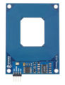 RFIDReader.jpg 250 × 326; 29 KB
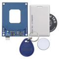 RFIDKit.jpg 250 × 250; 20 KB
 Rfid diag.bmp 309 × 277; 251 KB
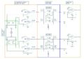
 Lcd circuit.gif 908 × 741; 176 KB
 Circuitdiagram.jpg 760 × 410; 29 KB
 Circuitdiagram EEPROM.jpg 760 × 410; 29 KB
 Graph.jpg 668 × 446; 28 KB
 Mini-tone transducer 637 × 504; 8 KB
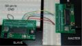
 SD Demo Operation.jpg 861 × 753; 33 KB
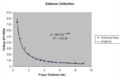 Distance Calibration.jpg 678 × 445; 24 KB
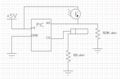 Detector circuit.jpg 587 × 384; 56 KB
 Rock paper scissors.jpg 750 × 600; 61 KB
 James and Chris 448 × 301; 31 KB
 Fish setup.bmp 483 × 460; 652 KB
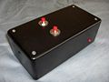
 Mrh box.jpg 450 × 600; 39 KB
 Mrg aequalsv2overr.jpg 80 × 48; 525 bytes
 Chladni 1speaker setup 704 × 528; 198 KB
 Team 12 Mechatronics 2009.jpg 380 × 336; 24 KB
 Chladni zeros circular plate 340 × 38; 8 KB
 SM Main Labeled.bmp 484 × 326; 155 KB
 Main RAW.bmp 484 × 326; 155 KB
- SM Classify.m ; 94 bytes
 Team12mech2009cktwiki.jpg 1,057 × 768; 59 KB
- SM ServoController.c ; 4 KB
- SM Matlab Servo Controller.c ; 4 KB
 Color sensor circuit diagram B.GIF 649 × 318; 6 KB
 Color sensor circuit diagram G.GIF 648 × 301; 6 KB
 Color sensor circuit diagram R.GIF 647 × 316; 6 KB
 Epuck xbee board version 2.gif 680 × 612; 21 KB
 E-puck XBee board version 1.gif 680 × 612; 20 KB
 Color sensor circuit diagram R.gif 647 × 316; 6 KB
 Color sensor circuit diagram G.gif 648 × 301; 6 KB
 Color sensor circuit diagram B.gif 647 × 316; 6 KB
 ESSE flow.jpg 898 × 626; 104 KB
- 123.zip ; 781 KB
 IMG 8568.JPG 313 × 345; 37 KB
- F hat 16 × 22; 902 bytes
 Gijoe datasheet.jpg 832 × 1,280; 151 KB
 Rps reciever.JPG 2,592 × 1,944; 793 KB
 MarionetteTeam.JPG 320 × 240; 14 KB
- USB.svg ; 76 KB
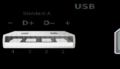 USBConnectors.jpg 700 × 400; 23 KB
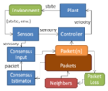 Swarm simlulator control structure.png 506 × 430; 31 KB
 3D calc code.ogg ; 3 KB
- 3D calc code.jpg ; 3 KB
- Here ; 415 KB
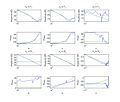 Bode plots 1.jpg 835 × 713; 64 KB
 Color sensor circuit diagram v2 R.gif 486 × 237; 8 KB
 Color sensor circuit diagram v2 G.gif 486 × 226; 8 KB
 Color sensor circuit diagram v2 B.gif 487 × 239; 8 KB
- 399UffordMonkeyBotSim.pdf ; 140 KB
- 399MonkeyBotCode commented.zip ; 11 KB
 Electric Compass PWM Wiring.jpg 1,420 × 947; 183 KB
 JR-matlab-gui.jpg 693 × 542; 120 KB
- 399MonkeyBotCode v2.zip ; 468 KB
- 399WriteupMonkeyBotSim-v2.pdf ; 379 KB
- 399UffordMonkeyBotSim-v2.pdf ; 379 KB
- UBW32 driver.zip ; 6 KB
- HID Bootloader v2 4 ; 27 KB
- HelloUSBWorldPic32.zip ; 4 KB
- Release NotesC.pdf ; 356 KB
 Setuo.jpg 962 × 630; 38 KB
 Mattel-Football.jpg 332 × 500; 23 KB
- Jose-144-linux.zip ; 13.95 MB
- RCservoSoftPIC32.zip ; 2 KB
- RGB Swarm MATLAB 09-03-09.zip ; 26 KB
 PCBArtist Sch WizardStart.jpeg 972 × 441; 40 KB
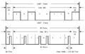
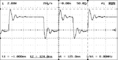 Test1-whileloop-onoff-pair.png 512 × 255; 7 KB
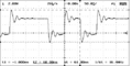 Test1-whileloop-onoff-timetogohigh.png 512 × 255; 7 KB
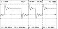 Test1-whileloop-onoff-timetogolow.png 512 × 255; 7 KB
- Lab5-team26-main.c ; 7 KB
- PIC scale convert.zip ; 97 KB
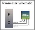 Lab5.2010.Transmt.Schmt.jpeg 437 × 370; 29 KB
 Lab5.2010.Transmt.Schmt.png 437 × 370; 29 KB
 Lab5.2010.Receive.Crct.png 652 × 522; 44 KB
 Lab5.2010.Crct.png 708 × 271; 45 KB
 George Randolph.Team15.2010.jpeg 480 × 640; 58 KB
 Lab5.2010.Circuit.png 702 × 265; 45 KB
- Nrf24l01 tutorial 1 pic18.pdf ; 177 KB
 EB WF BK Circuit diagram2.png 773 × 484; 21 KB
 USB.jpeg 626 × 600; 36 KB
 Usb.jpg 626 × 600; 36 KB
- Processing lab5.zip ; 27 KB
- Lab5-021110.zip ; 190 KB
 Kpmw userinterface.jpg 490 × 490; 33 KB
 ELECTRONICS.jpg 800 × 600; 171 KB
 Team26-dom.GIF 786 × 448; 14 KB
 Team26-dop.GIF 787 × 449; 13 KB
 Team26-window.GIF 1,005 × 733; 43 KB
 Team26-window2.GIF 1,006 × 730; 39 KB
- 27 CircuitDiagram.pdf ; 104 KB
 24-Drake-Ramsey.jpg 640 × 480; 86 KB
 Heartrate monitor.JPG 1,142 × 401; 45 KB
 Entire setup.jpg 3,872 × 2,592; 496 KB
 TR JP PP-sensor.jpg 250 × 167; 56 KB
 Furuta.JPG 3,872 × 2,592; 2.87 MB
 TR JP PP-AD9833 circuit.jpg 646 × 399; 29 KB
 TR JP PP-AD9833 Pic.jpg 1,600 × 1,200; 941 KB
 Furuta circuit.png 937 × 708; 83 KB
 Working pendulum.png 719 × 459; 517 KB
- Furuta code.c ; 6 KB
 Photo 81.jpg 172 × 200; 24 KB
 Overall.png 575 × 792; 51 KB
 MotorControlCircutTeam22.jpg 600 × 301; 27 KB
 Team26-limitswitch.jpg 1,600 × 1,200; 952 KB
 Team26-motor.jpg 2,816 × 2,112; 1.61 MB
- Final electrosense.zip ; 14 KB
 ButterflyCircuitDiagram2.jpg 1,145 × 859; 79 KB
- PIC electrosense.zip ; 122 KB
- Motor circuit.png ; 51 KB
- Motor circuit.pdf ; 51 KB
 Assembly.jpg 800 × 483; 77 KB
 ButterflyCircuitDiagram3.jpg 1,145 × 859; 80 KB
 ME333 2010 ButterflyDisc v2.jpg 516 × 464; 73 KB
 Kpmw ferrofluidcorrugation.jpg 418 × 242; 52 KB
 2dofYoutubeLink.jpg 634 × 356; 40 KB
 Group with butterfly.jpg 448 × 300; 34 KB
- Mobile Robot - Code.zip ; 11 KB


