Uncategorized files
From Mech
Jump to navigationJump to searchShowing below up to 500 results in range #751 to #1,250.
View (previous 500 | next 500) (20 | 50 | 100 | 250 | 500)
 EBell-MiscFigures.zip ; 527 KB
- EBell-P123.zip ; 3.05 MB
- EBell-P123v2.zip ; 3.17 MB
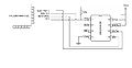
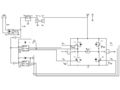
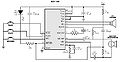
 EEPROM circuitdiagram.jpg 745 × 390; 28 KB
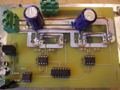
 ELECTRONICS.JPG 800 × 600; 171 KB
 ELECTRONICS.jpg 800 × 600; 171 KB
 ESSE flow.gif 898 × 626; 104 KB
 ESSE flow.jpg 898 × 626; 104 KB
 E Puck Color Sensing Circuit 1.gif 125 × 203; 2 KB
 E Puck Color Sensing Circuit 2.gif 256 × 203; 2 KB
 E Puck Color Sensing Circuit 3.gif 125 × 203; 2 KB
 E puck LED board.jpg 450 × 600; 33 KB
 E puck XBee board2.JPG 450 × 600; 31 KB
 EagleCommandList.jpg 468 × 467; 62 KB
 EaglePCBBreakout.jpg 468 × 205; 73 KB
 EagleSchematic.jpg 402 × 306; 37 KB
 Eagle Manual.pdf ; 4.44 MB
- Eagle Rules.pdf ; 25 KB
- Eagle Tutorial.pdf ; 856 KB
- Eagle job lib 2011-04-18.zip ; 708 KB
 Edge triggering symbol.gif 274 × 114; 1 KB
 Edit trace.jpg 884 × 632; 133 KB
 Eeprom1.jpg 400 × 300; 190 KB
 Eeprom2.JPG 400 × 401; 47 KB
 Eeprom rand access.c ; 3 KB
 ElectretMicrophone.gif 500 × 251; 7 KB
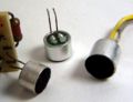 Electret condenser microphone capsules.jpg 829 × 638; 86 KB
 Electric Compass.jpg 935 × 623; 86 KB
 Electric Compass Full Wiring.jpg 1,337 × 891; 177 KB
 Electric Compass I2C Timing.jpg 1,694 × 546; 127 KB
 Electric Compass PWM Signal.jpg 768 × 576; 89 KB
 Electric Compass PWM Wiring.jpg 1,420 × 947; 183 KB
 Electric Compass Pin Out.jpg 1,200 × 647; 139 KB
- Embedded Computing V1.0-Nov 2015.zip ; 142 KB
- Embedded Computing V1.1-Mar 2016.zip ; 142 KB
- Embedded Computing V1.2-Apr 2016.zip ; 178 KB
 Emitter detector pair.gif 287 × 273; 1 KB
 Emitter follower voltage regulator.gif 294 × 220; 1 KB
 Encoder-maxon.jpg 901 × 305; 62 KB
- Encoder.docx ; 36 KB
 Encoder.png 894 × 605; 658 KB
 Encoder cable.jpg 406 × 363; 47 KB
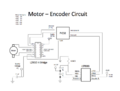
 Encoder diagram.png 539 × 293; 32 KB
 Encoder disk.jpg 800 × 600; 38 KB
 Encoder parts.png 658 × 270; 249 KB
 Encoderpins.jpg 956 × 785; 79 KB
 Encoderplug.gif 300 × 177; 2 KB
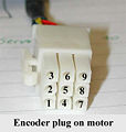 Encoderplug.jpg 300 × 317; 23 KB
 EncodersTeam22.jpg 2,592 × 1,849; 283 KB
 Entire Fish Refuge 448 × 324; 80 KB
 Entire setup.jpg 3,872 × 2,592; 496 KB
- EpuckMonitor.zip ; 378 KB
- Epuck xbee board v2.PCB ; 16 KB
 Epuck xbee board v2.gif 680 × 612; 21 KB
- Epuck xbee board v2.zip ; 3 KB
 Epuck xbee board version 2.gif 680 × 612; 21 KB
- Epuckbootloader.zip ; 37 KB
- Epuckprod b 12.pdf ; 1.27 MB
 ErrorPlot.jpg 499 × 393; 90 KB
- EssentialC.pdf ; 85 KB
 Ethernet interface cable.jpg 400 × 300; 36 KB
 Evitt-Miller-Mui.JPG 640 × 480; 111 KB
 Example.jpg 885 × 476; 138 KB
 Example.kirchhoff problem2 solution 2.gif 400 × 300; 5 KB
- ExamplePaperRSS2008.zip ; 1.51 MB
 Example oscilloscope reading.jpg 892 × 569; 105 KB
- ExpValOfSwarmFormation.pdf ; 6.1 MB
 Exp schematic.jpg 497 × 456; 17 KB
 Expected Output.png 692 × 942; 382 KB
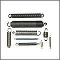 Extensionsprings.jpg 240 × 240; 10 KB
 External Ram PIC32 SPI.png 782 × 406; 22 KB
 Extractor.jpg 300 × 175; 13 KB
 FChronos.svg 607 × 291; 15 KB
 FFT 1K sin.jpg 1,280 × 920; 88 KB
 FFT 1K square.jpg 1,280 × 920; 85 KB
 FFT 2K sin.jpg 1,280 × 920; 97 KB
 FFT 2K square.jpg 1,280 × 920; 103 KB
 FFT 3K sin.jpg 1,280 × 920; 100 KB
 FFT 500 sin.jpg 1,280 × 920; 78 KB
- FW B 20.hex ; 6 KB
 FX1901.jpg 283 × 209; 10 KB
 FX1901 Diagram.jpg 376 × 227; 11 KB
- F hat 16 × 22; 902 bytes
 F hat.gif 16 × 22; 902 bytes
- Faulhaber-datasheet.pdf ; 747 KB
 Faulhaber-pinout.jpg 339 × 236; 8 KB
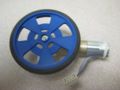 Faulhaber-wheel.jpg 307 × 230; 18 KB
 Faulhaber.png 500 × 375; 438 KB
 Ferrous sensor.jpg 632 × 342; 20 KB
 Ferrous sensor operation.jpg 695 × 287; 14 KB
 FftSchematic.png 818 × 690; 31 KB
 Field of view.gif 960 × 720; 3 KB
 Fig1.gif 500 × 251; 7 KB
 Filtering example.png 791 × 656; 198 KB
 Filters.jpg 640 × 399; 58 KB
- Final-Assignment-2014-part1.pdf ; 97 KB
- FinalDemo.zip ; 2.94 MB
- FinalProject.zip ; 2.95 MB
- FinalProjectV2.zip ; 2.95 MB
- Final Circuit.zip ; 34 KB
 Final Design.jpg 810 × 577; 61 KB
- Final electrosense.zip ; 14 KB
- FingerPosition v05.pcb ; 90 KB
 Finger postition board.JPG 960 × 624; 66 KB
 Fire Control.png 3,072 × 2,245; 53 KB
 First.jpg 320 × 240; 5 KB
- Fish arm.prt ; 368 KB
- Fish box.prt ; 392 KB
- Fish quarter circle.prt ; 248 KB
- Fish quarter circle large.prt ; 248 KB
 Fish setup.bmp 483 × 460; 652 KB
- Fish setup.bmp 483 × 460; 652 KB
- Flexure Analysis.zip ; 69 KB
 Flexure GUI.jpg 1,497 × 847; 203 KB
 Flexure GUI.png 1,449 × 838; 80 KB
- Flexure Test.zip ; 422 KB
 Flexure setup.jpg 563 × 422; 209 KB
- Flexure test code.zip ; 413 KB
 Flexure test straight.jpg 422 × 640; 111 KB
 Fluff Bot 1.jpg 640 × 480; 379 KB
- Fluff bot PIC Code.zip ; 72 KB
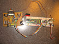 Fluffbot Circuit Boards.jpg 800 × 600; 841 KB
 Fluffbot Concept.jpg 511 × 259; 36 KB
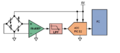
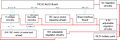 Fluffbot Electronics Block Diagram.jpg 798 × 263; 36 KB
- Fluffbot Processing.zip ; 1.04 MB
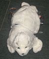 Fluffbot with Seal Housing.jpg 629 × 760; 115 KB
 Fluke multimeter.jpg 400 × 300; 56 KB
 Focal length.gif 960 × 720; 5 KB
 Focal plane.gif 960 × 720; 6 KB
 ForceSensorCircuitDiagram.jpg 521 × 319; 487 KB
 Force sensor.jpg 564 × 423; 102 KB
 Force sensor mount.jpg 634 × 476; 105 KB
 Form-closure.png 499 × 276; 27 KB
 Forward Pantograph Kinematics.png 403 × 280; 14 KB
- FourChar2Float.zip ; 4 KB
 Frank-park-headshot.jpg 130 × 162; 9 KB
 FullSnake.jpg 500 × 375; 72 KB
- Fun to delay.m ; 3 KB
 Function generator front.png 451 × 1,238; 93 KB
 Furuta.JPG 3,872 × 2,592; 2.87 MB
 Furuta.png 494 × 740; 468 KB
 Furuta circuit.png 937 × 708; 83 KB
- Furuta code.c ; 6 KB
 Furutapendulum.jpg 112 × 149; 10 KB
 GM3.png 500 × 375; 404 KB
- GP2YA60SZ.pdf ; 685 KB
 GPIOs.png 254 × 581; 38 KB
 GPS Circuit.jpg 846 × 635; 62 KB
 GPS Raw Data Stream 873 × 128; 25 KB
 GTPP Headset.JPG 410 × 309; 25 KB
 GTTP AD9833 Timing.jpg 749 × 231; 20 KB
 GTTP Algorithm.jpg 951 × 279; 79 KB
 GTTP Comparator behavior.jpg 450 × 300; 34 KB
 GTTP DC Drive.jpg 451 × 301; 72 KB
 GTTP Headset.JPG 410 × 309; 25 KB
 GTTP Headset.jpg 410 × 309; 25 KB
 GTTP Knob.jpg 422 × 289; 16 KB
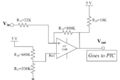
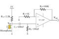 GTTP Microphone and preamplifier.jpg 451 × 301; 33 KB
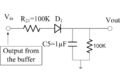 GTTP Rectify and filter.jpg 450 × 300; 31 KB
 GTTP System.jpg 1,932 × 1,720; 625 KB
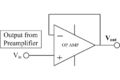 GTTP Voltage Buffer.jpg 451 × 301; 28 KB
 GTTP Voltage buffer.jpg 451 × 301; 28 KB
 GTTP Voltage comparator.jpg 451 × 301; 30 KB
 GTTP system.jpg 1,375 × 1,019; 362 KB
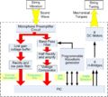
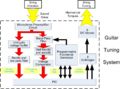
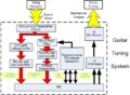 GTTP system diagram.jpg 451 × 331; 87 KB
 Gaussian random field.gif 246 × 39; 2 KB
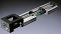
 Gear-ballscrew-small.gif 400 × 300; 36 KB
 Gear-ballscrew.gif 533 × 400; 105 KB
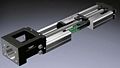
 Gear-ballscrew2-small.jpg 430 × 243; 22 KB
 Gear-ballscrew2.jpg 717 × 406; 72 KB
 Gear-efficiency.jpg 363 × 217; 19 KB
 Gear-harmonic-drive-anim.gif 200 × 200; 1.04 MB
 Gear-harmonicdrive.gif 515 × 189; 19 KB
 Gear-harmonicdrive2aligned.jpg 979 × 690; 126 KB
 Gear-helical2.jpg 400 × 267; 14 KB
 Gear-planetary-anim.gif 200 × 200; 118 KB
 Gear-planetary.jpg 430 × 469; 19 KB
 Gear-planetarystage.jpg 403 × 256; 30 KB
 Gear-speed-torque.jpg 276 × 227; 16 KB
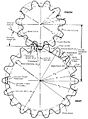 Gear-spurdetails.jpg 495 × 672; 83 KB
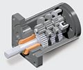
 Gear-spurgearhead.jpg 281 × 240; 15 KB
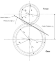 Gear circle geometry.png 661 × 713; 52 KB
 Gear spurgearhead.jpg 281 × 240; 15 KB
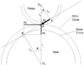 Gear triangles.png 714 × 551; 20 KB
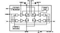
 General Bipolar H-Bridge Drive Circuit.JPG 690 × 382; 58 KB
 General model.gif 217 × 54; 2 KB
 Geo.jpg 619 × 279; 27 KB
 George Randolph.Team15.2010.jpeg 480 × 640; 58 KB
 George Randolph.jpg 480 × 640; 58 KB
- GiJoe.c ; 12 KB
 Gijoe arm.jpg 972 × 1,296; 108 KB
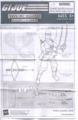 Gijoe datasheet.jpg 832 × 1,280; 151 KB
- Globe-cad.pdf ; 93 KB
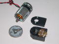 Globe-dissassembled.jpg 2,304 × 1,728; 454 KB
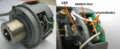
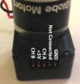 Globe-encoder-annotated.jpg 732 × 769; 83 KB
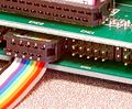
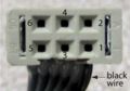
 Globe-encoder-cable-molex.jpg 306 × 459; 38 KB
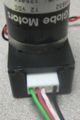
 Globe-encoder-cable.jpg 574 × 556; 76 KB
 Globe-encoder-removed.jpg 2,304 × 1,728; 432 KB
 Globe-exposed-pinion.jpg 1,052 × 783; 77 KB
 Globe-gearbox-annotated.jpg 1,019 × 763; 137 KB
 Globe-gearhead-closeup.jpg 1,200 × 900; 123 KB
 Globe-gearhead.jpg 1,200 × 900; 158 KB
 Globe-hex-wrench-inserted.jpg 1,024 × 730; 105 KB
 Globe-machined-motor-head.jpg 1,266 × 783; 99 KB
 Globe-motor.jpg 622 × 378; 44 KB
 Globe-nogearhead.jpg 645 × 484; 97 KB
 Globe-scredriver-inserted.jpg 1,102 × 761; 88 KB
 Gm3-01.jpg 300 × 184; 28 KB
 Gm3-02.jpg 300 × 167; 27 KB
 Gm3-03.jpg 300 × 171; 26 KB
 Gm3-04.jpg 300 × 196; 32 KB
 Gm3-05.jpg 300 × 214; 37 KB
 Gm3-06.jpg 300 × 197; 50 KB
 Gm3-07.jpg 300 × 152; 31 KB
 Gm3-08.jpg 300 × 250; 58 KB
 Gm3-09.jpg 300 × 219; 37 KB
 Gm3-10.jpg 300 × 245; 35 KB
 Gm3-11.jpg 300 × 217; 36 KB
 Gm3-12.jpg 300 × 311; 22 KB
 Gm3-13.jpg 300 × 198; 12 KB
 Gm3-14.jpg 300 × 206; 11 KB
 Gm3-15.jpg 300 × 223; 17 KB
 Gm3-16.jpg 300 × 188; 13 KB
 Gm3-18.jpg 300 × 167; 10 KB
- GradeSorter.c ; 2 KB
 Graph.jpg 668 × 446; 28 KB
 Gray.jpg 422 × 372; 19 KB
 Ground symbol.gif 100 × 100; 777 bytes
 Group 23.JPG 461 × 346; 38 KB
 Group with butterfly.jpg 448 × 300; 34 KB
 GuiScreenShot.jpg 867 × 746; 111 KB
 H-bridge-outs-small.jpg 614 × 461; 67 KB
 H-bridge-outs-small2.jpg 350 × 249; 37 KB
- H44780.pdf ; 322 KB
 HB calibration error.jpg 560 × 420; 35 KB
- HBridge L293D.pdf ; 862 KB
- HD44780 LCD ds.pdf ; 322 KB
- HEDS5500-encoder.pdf ; 372 KB
- HIDAPI.zip ; 39 KB
- HIDBootLoader.zip ; 27 KB
- HID Bootloader PIC18 Non J.hex ; 12 KB
- HID Bootloader PIC32.zip ; 25 KB
- HID Bootloader v2 4 ; 27 KB
- HID Bootloader v2 4.zip ; 27 KB
 HLSSnakeMain.jpg 500 × 375; 72 KB
 HPIM1027.JPG 648 × 488; 123 KB
 HPIM1027.jpg 648 × 488; 123 KB
- HW1 answers 2018ME449.pdf ; 962 KB
- HW2 answers 2018ME449.pdf ; 567 KB
- HW4 Interrupts and Programming.zip ; 189 KB
 HW PIC32 AddFile.jpg 272 × 397; 21 KB
 HW PIC32 BoardDefine.jpg 446 × 551; 50 KB
 HW PIC32 Include.jpg 446 × 551; 47 KB
 HW PIC32 ProjectWindow1.jpg 274 × 394; 21 KB
 HW PIC32 ProjectWindow2.jpg 272 × 397; 21 KB
 Half b.jpg 300 × 230; 8 KB
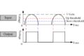
 Half wave rectifier graph.gif 436 × 198; 14 KB
 Half wave rectifier schematic.gif 314 × 226; 4 KB
 Hall Sensors.jpg 874 × 643; 64 KB
 Hall effect sensor.jpg 539 × 417; 33 KB
 Hall effect switch.jpg 378 × 370; 8 KB
 Hallsensorcircuit.jpg 626 × 385; 22 KB
 Hallsensorsetup.jpg 800 × 650; 90 KB
- HapticInterfaceSourceCode.zip ; 97 KB
 HapticsBlockDiagram.png 539 × 219; 12 KB
 Haptikos.jpg 600 × 655; 88 KB
 Harmonic gears.jpg 680 × 313; 37 KB
- Hazelrigg-IMECE2016.pdf ; 903 KB
 Hbridge PCB top view.JPG 855 × 642; 226 KB
 Hbridge schem v1.jpg 720 × 540; 31 KB
- Hbridge v4.pcb ; 74 KB
 Hd44780-interface-lcd-4bit.gif 506 × 528; 4 KB
 Heart rate sensor mfth.JPG 836 × 718; 79 KB
 Heartrate monitor.JPG 1,142 × 401; 45 KB
 Heartrate monitor.PNG 1,030 × 373; 24 KB
 Heatshrink x.gif 300 × 184; 3.29 MB
 Helical gears.png 251 × 216; 72 KB
- HelloUSBWorldPic32.zip ; 4 KB
- HelloWorld NU32.zip ; 4 KB
- HelloWorld PIC32.zip ; 4 KB
- HelloWorld PIC32 Hex.zip ; 4 KB
- HelloworldForNU32.zip ; 673 bytes
- Helloworld for NU32.zip ; 624 bytes
- Here ; 415 KB
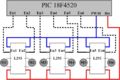
- HexInverter 74HC04.pdf ; 109 KB
- Hidapi-1.1-javadoc.zip ; 44 KB
 High speed schematic.jpg 1,218 × 975; 120 KB
 Hitachi-motor.jpg 1,052 × 736; 163 KB
 Horizontal arm.png 909 × 608; 807 KB
 Hostscope1.jpg 400 × 220; 14 KB
 Hostscope2.jpg 400 × 351; 26 KB
 Hostscope3.jpg 600 × 343; 39 KB
 Housing.jpg 500 × 375; 42 KB
 Human-arm.png 914 × 1,607; 213 KB
 Hysteresiscomparatorcircuit.JPG 481 × 428; 21 KB
 Hysteresiscomparatorcircuit.jpg 481 × 428; 21 KB
 Hysteresiscomparatoroutput.jpg 763 × 347; 30 KB
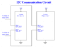
 I2C.jpg 754 × 260; 22 KB
- I2CMotorController.PDF ; 482 KB
- I2CMotorControllerCode.zip ; 10 KB
- I2C ADC.c ; 2 KB
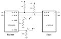
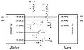 I2C Alternate Circuit Diagram 1,203 × 716; 62 KB
- I2C Alternate Master.c ; 2 KB
- I2C Alternate Slave.c ; 2 KB
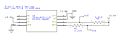
 I2C Circuit Diagram.jpg 1,214 × 774; 55 KB
- I2C DAC.c ; 1 KB
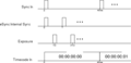
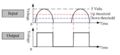
 I2C Data Transfer.jpg 837 × 140; 16 KB
 I2C Data Transfer.svg ; 12 KB
- I2C Master.c ; 1 KB
- I2C RAM.c ; 2 KB
 I2C RAM.jpg 1,127 × 466; 122 KB
 I2C Schematic.jpg 970 × 507; 27 KB
- I2C Slave.c ; 793 bytes
 I2C Wiring Image.jpg 978 × 529; 125 KB
 I2C circuit.PNG 516 × 413; 11 KB
 I2c-dac.gif 576 × 286; 10 KB
 I2c eeprom RC3 pullout.jpg 1,152 × 864; 126 KB
 I2c eeprom circuit.jpg 896 × 518; 29 KB
 I2c eeprom circuit picture.jpg 1,152 × 864; 126 KB
 ICD2.jpg 420 × 336; 19 KB
 ICD2 driver.jpg 503 × 392; 43 KB
 ICDfull.jpg 542 × 225; 29 KB
 ICDpic.JPG 300 × 225; 27 KB
- IFFTcode.zip ; 6 KB
- IFFTcode2.zip ; 6 KB
 IFFTwaveforms.png 1,680 × 938; 18 KB
 IFFTwaveforms2.png 1,680 × 938; 18 KB
 IFftSchematic.png 812 × 789; 43 KB
- IHZ7KO7zz.pdf ; 140 KB
- IKexercise.pdf ; 983 KB
 IMG 1390-1-.jpg 800 × 600; 193 KB
 IMG 8568.JPG 313 × 345; 37 KB
 IMSE of LLR.jpg 438 × 66; 6 KB
- IMjurboSX9.pdf ; 109 KB
- IMn5LDZcb.pdf ; 141 KB
- INT core timer.c ; 1 KB
- INT ext int.c ; 1 KB
- INT timing.c ; 2 KB
 IR Detector Emitter.jpg 854 × 633; 60 KB
- IR Tracker.c ; 11 KB
 IR Tracker.jpg 753 × 594; 37 KB
- IR Tracker Code.c ; 10 KB
 IR Tracker Header.jpg 400 × 514; 29 KB
 IR Tracker Main.jpg 912 × 607; 103 KB
 IR Tracker Team.jpg 640 × 480; 103 KB
 IR circuit.jpg 679 × 325; 26 KB
 ISD1110 Circuit 1,567 × 816; 98 KB
- IV5TBTy6xN.pdf ; 109 KB
- IaDdfwHBoJ.pdf ; 108 KB
- Ic3ad7nItp.pdf ; 107 KB
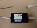
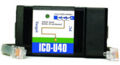 Icd-u40.jpg 350 × 191; 27 KB
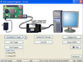 Icdtest.jpg 584 × 438; 87 KB
- IdYC8MpqX.pdf ; 141 KB
 IdentiyGame.jpg 629 × 534; 9 KB
- Idss-connector.pdf ; 820 KB
- IfdCvbFgh.pdf ; 140 KB
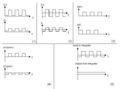 Illustration of the example PSD circuit.jpg 589 × 435; 23 KB
 Image-Mechanical Design Labels.bmp 189 × 252; 140 KB
 Image plane.gif 960 × 720; 4 KB
 Img-pta.jpg 1,152 × 1,536; 1.51 MB
 Img-wc1.jpg 1,280 × 960; 220 KB
 Img-wc2.jpg 1,280 × 960; 184 KB
 Img-wc3.jpg 1,280 × 960; 184 KB
 Img-wc4.jpg 717 × 960; 136 KB
 Img0067b.jpg 300 × 151; 28 KB
 Img0162.jpg 300 × 166; 29 KB
 Img0163.jpg 300 × 228; 36 KB
 Img0165.jpg 300 × 185; 34 KB
 Img0166.jpg 300 × 174; 21 KB
 Img0168.jpg 300 × 176; 29 KB
 Img0170.jpg 300 × 182; 29 KB
- Img0174.jpgImg0174.jpg File missing
 Img0180.jpg 300 × 226; 26 KB
 Img0182.jpg 300 × 157; 27 KB
 Increment.jpg 352 × 268; 14 KB
- IndentifyGame.zip ; 3 KB
 Indexer.png 552 × 271; 9 KB
 Inductor symbol.gif 100 × 100; 553 bytes
 Inductors photo.jpg 800 × 600; 120 KB
- Input capture.c ; 6 KB
 InstAmp2.gif 544 × 242; 3 KB
 Instr amp 7805 pic.jpg 222 × 208; 45 KB
 Instr amp 7805 schematic.gif 365 × 454; 6 KB
 Instr amp INA129.gif 117 × 120; 1 KB
 Instr amp LED.jpg 83 × 137; 26 KB
 Instr amp Peshkin.gif 310 × 49; 5 KB
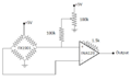
 Instr amp bridge schematic.gif 288 × 322; 2 KB
 Instr amp filter capacitor schematic.gif 457 × 504; 4 KB
 Instr amp input common mode range.gif 400 × 321; 15 KB
 Instr amp inside.gif 600 × 331; 14 KB
 Instr amp pcb batteries.jpg 220 × 162; 42 KB
 Instr amp pcb dcdc.jpg 533 × 286; 83 KB
 Instr amp pcb diodes.jpg 44 × 132; 20 KB
 Instr amp pcb wheatstone.jpg 41 × 174; 22 KB
 Instr amp pinout.gif 817 × 198; 11 KB
 Instr amp power wire jump.jpg 393 × 195; 37 KB
 Instr amp powerplug.jpg 95 × 179; 25 KB
 Instr amp protoarea pic.jpg 301 × 188; 55 KB
 Instr amp protoarea schematic.gif 289 × 264; 9 KB
 Instr amp terminal strip.jpg 204 × 159; 43 KB
 Instr amp trimpot pic.jpg 136 × 150; 33 KB
 Instr amp trimpot schematic.gif 573 × 328; 9 KB
 Instr amp wheatstone bridge.gif 315 × 220; 2 KB
 Instr amp whole pcb layout.png 1,490 × 734; 24 KB
 Instr amp whole schematic.gif 960 × 546; 20 KB
 Instr amp whole schematic.png 960 × 546; 20 KB
 Instr amp with wheatstone schematic.gif 400 × 214; 5 KB
 Insulator diagram.gif 273 × 202; 4 KB
 Inverse Pantograph Kinematics.png 347 × 270; 13 KB
 Inverter gate symbol.gif 150 × 150; 520 bytes
- Invest.c ; 6 KB
 Ir connect.jpg 2,295 × 990; 427 KB
 Ir source.jpg 2,367 × 1,410; 530 KB
 Ir transceiver.jpg 1,278 × 1,140; 197 KB
 Irfu.jpg 300 × 463; 35 KB
 Iririr.jpg 300 × 204; 13 KB
 Isometric view of Fluffbot guts.jpg 2,048 × 1,536; 159 KB
- Iterative Learning Control 423 × 854; 282 KB
 JFET n.gif 150 × 150; 465 bytes
 JFET p.gif 150 × 150; 456 bytes
 JK flipflop symbol.gif 192 × 220; 2 KB
 JK flipflop timing.gif 451 × 314; 5 KB
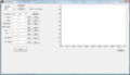
 JR-matlab-gui.jpg 693 × 542; 120 KB
 JR-matlab-gui2.jpg 800 × 460; 113 KB
- JS JW Wii Demo.zip ; 180 KB
- JVEEhlznPo.pdf ; 176 KB
- Jameco-solenoid-262262.pdf ; 312 KB
- Jameco-stepper-162026.pdf ; 406 KB
- Jameco-stepper-163395.pdf ; 316 KB
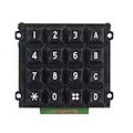 Jameco16buttonkeypad.jpg 150 × 150; 7 KB
- Jameco Solenoid Part142464.pdf ; 211 KB
 James and Chris 448 × 301; 31 KB
- James and Chris 448 × 301; 31 KB
 Jd-cr-Assembly.jpg 800 × 483; 77 KB
 Jd-cr-Full-schematic.jpg 800 × 600; 54 KB
- Jose-144-linux.zip ; 13.95 MB
 Junus acmd.jpg 274 × 337; 16 KB
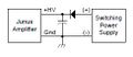
 Junus amp pin diagram.png 471 × 216; 29 KB
 Junus iloop.jpg 493 × 396; 26 KB
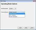 Junus mode.jpg 416 × 351; 18 KB
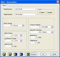 Junus param.jpg 478 × 456; 40 KB
 Junus power.jpg 244 × 105; 5 KB
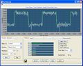 Junus scope.jpg 746 × 596; 83 KB
 Just5.jpg 200 × 150; 4 KB
- K6qzyYOWmW.pdf ; 174 KB
- KHONFi4jAM.pdf ; 174 KB
- KOtaVsYKa0.pdf ; 174 KB
 Kevin-lynch-headshot.jpg 130 × 162; 15 KB
 Kevin-m-lynch-headshot.jpg 130 × 162; 15 KB
 Keyboard interface cable.jpg 400 × 300; 38 KB
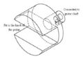
 Keyway.jpg 151 × 160; 14 KB
 Kilobot-img.png 1,201 × 849; 574 KB
 Kircchoff ex1 loopsandnodes.gif 400 × 300; 4 KB
 Kirchhoff ex1 currentarraow.gif 400 × 300; 4 KB
 Kirchhoff example1 1.gif 400 × 300; 4 KB
 Kirchhoff example2-1.gif 400 × 300; 7 KB
 Kirchhoff example2-2.gif 400 × 300; 12 KB
 Kirchhoff example2-3.gif 400 × 300; 9 KB
 Kirchhoff example2-4.gif 400 × 300; 12 KB
 Kirchhoff example2 currentarrow.gif 400 × 300; 5 KB
 Kirchhoff example 1.gif 400 × 300; 6 KB
 Kirchhoff problem2 solution 1.gif 336 × 209; 4 KB
 Kirchhoff problem 1.gif 400 × 300; 6 KB
 Kirchhoff problem 2.gif 400 × 300; 7 KB
 Kirchhoff sign conventions.gif 500 × 100; 4 KB
 Kirchhoff voltage law analysis1.gif 300 × 300; 4 KB
 Kirchhoff voltage law analysis2.gif 300 × 300; 4 KB
 Kirchhoff voltage law loop.gif 400 × 300; 11 KB
 Kirchhoff voltage law paths.gif 400 × 300; 8 KB
 Kirchhoffs current law node2.gif 400 × 300; 4 KB
 Kirchhoffs current law node diagram.gif 400 × 300; 6 KB
- Kp mw tp ME333PIC32Benchmarking.zip ; 100 KB
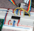
 Kp mw tp benchmarkingcircuit2010.jpg 424 × 200; 35 KB
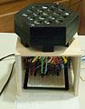 Kpmw Ferrofluid.jpg 238 × 305; 44 KB
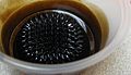 Kpmw ferrofluidcorrugation.jpg 418 × 242; 52 KB
 Kpmw userinterface.jpg 490 × 490; 33 KB
 Kpmw userinterface.png 478 × 498; 15 KB
- L293.pdf ; 194 KB
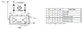
 L293D.jpg 400 × 361; 55 KB
- L293D.pdf ; 488 KB
- L293D TI.pdf ; 470 KB
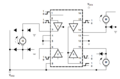
 L293D bidirectional.png 1,016 × 361; 36 KB
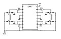
 L293D circuitdiagram.png 857 × 561; 35 KB
 L293D truthtable.png 391 × 322; 19 KB
 L293b.jpg 850 × 550; 36 KB
- L297.pdf ; 165 KB
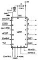 L297.png 200 × 314; 10 KB
- L297 and L298.pdf ; 172 KB
 L297 pinout.jpg 289 × 394; 16 KB
- L298N.pdf ; 595 KB
- L3GD20H.pdf ; 2.42 MB
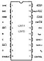
 L6201.jpg 761 × 424; 40 KB
- L6234.pdf ; 490 KB
- LAB5-SD Card Reader.zip ; 389 KB
 LAB5 Force Sense Block Diagram.png 456 × 200; 10 KB


