Uncategorized files
From Mech
Jump to navigationJump to searchShowing below up to 250 results in range #251 to #500.
View (previous 250 | next 250) (20 | 50 | 100 | 250 | 500)
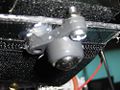
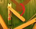
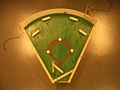
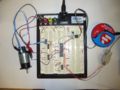
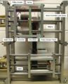
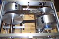
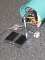
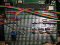
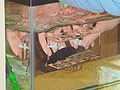 Automated Fish Refuge CloseupFish 1,600 × 1,200; 774 KB
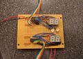
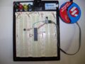
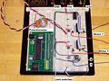
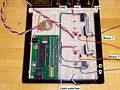
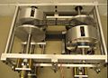
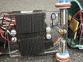
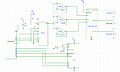
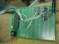 Automated fish refuge circuit.jpg 1,600 × 1,200; 878 KB
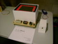
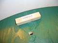
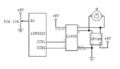
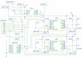
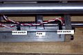
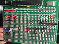
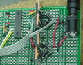 Automated fish refuge closecircuit.jpg 628 × 490; 223 KB
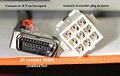
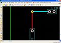 Automatic via.jpg 886 × 633; 105 KB
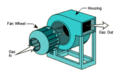
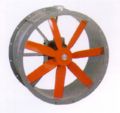 AxialFanPicture.JPG 640 × 600; 96 KB
 B57164K.pdf ; 579 KB
 BKSBallControl.fig ; 7 KB
- BKSBallControl.m ; 22 KB
 BKSBallMasterv1.c ; 4 KB
- BKSBallSlave1v1.c ; 8 KB
- BKSBallSlavev1.c ; 8 KB
- BPI 216 Send v1.zip ; 12 KB
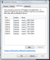 BT COM ports.png 385 × 460; 28 KB
 BallCaster.jpg 500 × 375; 63 KB
 Ballbalancechallenge.JPG 2,816 × 2,112; 2.5 MB
 Barrel.jpg 400 × 238; 17 KB
 Base.png 321 × 414; 189 KB
 Baseball Ball Sensor.jpg 1,052 × 900; 150 KB
 Baseball Base LED.jpg 903 × 777; 77 KB
 Baseball Bat.jpg 1,122 × 930; 108 KB
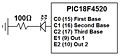 Baseball LED circuitry.jpg 453 × 211; 17 KB
 Baseball PIC Circuitry.jpg 814 × 1,135; 155 KB
 Baseball Pitcher.jpg 1,268 × 948; 155 KB
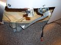
 Baseball Playfield.jpg 1,264 × 952; 199 KB
 Baseball Recess.jpg 1,276 × 960; 174 KB
 Baseball Relay.jpg 944 × 1,115; 106 KB
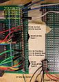
 Baseball Scoreboard Circuitry.jpg 1,156 × 824; 181 KB
 Baseball Sensor.jpg 1,052 × 900; 150 KB
 Baseball Single.jpg 1,268 × 936; 96 KB
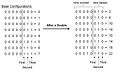 Baseball array explanation.jpg 867 × 526; 54 KB
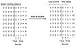 Baseball array explanation2.jpg 896 × 526; 54 KB
- Baseball final.c ; 7 KB
- Baseball fullcode.c ; 7 KB
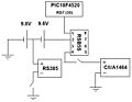 Baseball pitcher bat circuitry.jpg 698 × 540; 27 KB
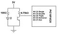 Baseball sensor circuitry.jpg 672 × 394; 23 KB
 Basic model.jpg 228 × 42; 3 KB
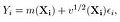
 Battery pack.jpg 400 × 300; 39 KB
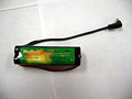
 Battery pack charger.jpg 400 × 300; 54 KB
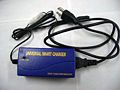
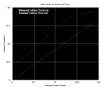
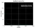 BaudRate.vs.Latency.png 539 × 435; 30 KB
- Berard-Egan-Trinkle-ICRA2004.pdf ; 154 KB
- BerardTechReport.pdf ; 224 KB
 Bergquist hand ball balancing.jpg 216 × 222; 52 KB
 Bevel gears.png 154 × 176; 12 KB
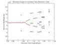 BifDiag Small.jpg 560 × 420; 26 KB
 Binary.jpg 422 × 372; 22 KB
 Bipolar.gif 338 × 158; 2 KB
 Bipolar2input.png 360 × 200; 1 KB
 Bipolar4input.png 516 × 398; 2 KB
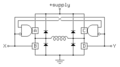
 Bipolar Stepper Motor Drive Circuit JSJW.JPG 1,189 × 697; 56 KB
 Bipolaranim.gif 340 × 159; 36 KB
 Bipolarstepper.gif 338 × 158; 2 KB
 Bipwmckt.jpg 470 × 272; 24 KB
- Bix-IMECE2016.pdf ; 13.67 MB
 Block-capstone.png 1,336 × 1,138; 138 KB
- Blockdiag.jpg 740 × 436; 98 KB
 Blown-up-battery.jpg 1,035 × 630; 217 KB
- BoB partslist 526 2005-12-14.xls ; 30 KB
- BoB partslist 526 2005-12-28.xls ; 30 KB
 Board size.jpg 708 × 584; 59 KB
 Bobbot.jpg 2,048 × 1,536; 377 KB
 Bobtop.jpg 2,048 × 1,536; 417 KB
 Bode plots 1.bmp 834 × 713; 583 KB
 Bode plots 1.jpg 835 × 713; 64 KB
- Book-current.pdf ; 38.76 MB
- Book-draft-April1-2015.pdf ; 64.21 MB
- Boot600.zip ; 641 KB
- Bootloader.zip ; 119 KB
- Bouncing Ball Simulator.zip ; 5 KB
 Bouncing switch.jpg 372 × 276; 40 KB
 Box.png 912 × 608; 795 KB
 Bpgain.jpg 376 × 221; 17 KB
 Bps-nrf24l01.jpg 560 × 420; 31 KB
- Brass cylinder.zip ; 20 KB
 Breadboard ac adapter.jpg 400 × 300; 51 KB
 Breadboard large.jpg 400 × 300; 68 KB
 Breadboard small.jpg 400 × 300; 61 KB
 BuiltChasis.jpg 500 × 375; 67 KB
 BuiltChasis2 MLS.jpg 2,304 × 1,728; 1.78 MB
 ButterflyCircuitDiagram.jpg 1,240 × 958; 234 KB
 ButterflyCircuitDiagram2.jpg 1,145 × 859; 79 KB
 ButterflyCircuitDiagram3.jpg 1,145 × 859; 80 KB
- ButterflyFinalCode.zip ; 113 KB
 Butterfly Circuit.jpg 448 × 309; 78 KB
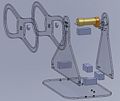 Butterfly Exploded View.jpg 915 × 768; 63 KB
- Butterfly Matlab code.zip ; 57 KB
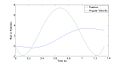 Butterfly Trajectory.jpg 1,280 × 682; 46 KB
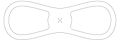 Butterfly shape.jpg 448 × 156; 14 KB
 Butterflyteampic.jpg 448 × 336; 32 KB
 Bypass cap.gif 318 × 165; 1 KB
 ByteSize.Vs.latency.png 616 × 512; 39 KB
 C18 tutorial ADC breadboard.jpeg 2,304 × 1,728; 1.76 MB
 C18 tutorial ADC wiring.gif 608 × 395; 19 KB
- C18 tutorial ADC wiring.ppt ; 47 KB
 C18 tutorial Motor controller DE9F.jpeg 1,600 × 1,200; 949 KB
 C18 tutorial Motor controller wiring.gif 925 × 680; 43 KB
 C18 tutorial add files.gif 296 × 403; 11 KB
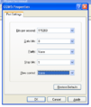 C18 tutorial hyperterminal choose baud.png 361 × 427; 22 KB
 C18 tutorial hyperterminal choose emulation.png 353 × 430; 28 KB
 C18 tutorial hyperterminal choose name.png 363 × 323; 15 KB
 C18 tutorial hyperterminal choose port.png 309 × 314; 12 KB
 C18 tutorial hyperterminal open.png 671 × 566; 180 KB
 C18 tutorial motor controller breadboard.jpeg 2,304 × 1,728; 1.76 MB
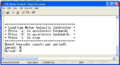 C18 tutorial welcome message.png 646 × 351; 21 KB
- CBook.pdf ; 3.49 MB
- CCCHelloWorld.c ; 79 bytes
- CCCbubble.c ; 641 bytes
- CCCdatasizes.c ; 754 bytes
- CCChelper.c ; 335 bytes
 CCChelper.h ; 355 bytes
- CCChexdump.c ; 1 KB
- CCCinvest.c ; 5 KB
- CCClights.c ; 1 KB
- CCCmain.c ; 295 bytes
- CCCoverflow.c ; 421 bytes
- CCCprintout.c ; 298 bytes
- CCCtypecast.c ; 497 bytes
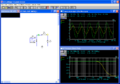 CM AC sweep graph.png 990 × 692; 56 KB
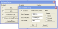 CM AC sweep setup.png 528 × 268; 15 KB
 CM DC sweep 1src graph.png 1,017 × 699; 39 KB
 CM DC sweep 1src setup.png 445 × 318; 14 KB
 CM DC sweep 2src.png 1,012 × 278; 9 KB
 CM DC sweep ciruict.gif 374 × 232; 2 KB
 CM LPF circuit.gif 294 × 193; 1 KB
 CM LPF graph.png 1,018 × 694; 40 KB
 CM LPF graph2.png 1,017 × 279; 10 KB
 CM RC circuit.gif 252 × 216; 1 KB
 CM RC discharge.gif 144 × 172; 678 bytes
 CM RC dishcarge IC.gif 188 × 166; 890 bytes
 CM RC exponential1.jpg 1,020 × 704; 155 KB
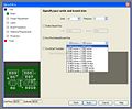
 CM add parts.jpg 290 × 184; 33 KB
 CM analog button.gif 104 × 26; 535 bytes
 CM capacitor IC graph.jpg 1,024 × 700; 143 KB
 CM capacitor IC set.jpg 336 × 431; 60 KB
 CM connected circuit.gif 160 × 219; 950 bytes
 CM digital mode button.gif 104 × 26; 485 bytes
 CM disconnected circuit.gif 184 × 165; 688 bytes
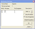 CM edit pin data.jpg 375 × 313; 45 KB
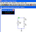 CM multimeter.jpg 444 × 400; 70 KB
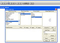 CM part menu.jpg 728 × 530; 102 KB
 CM pin numbers.gif 317 × 270; 2 KB
 CM probe tool.gif 26 × 23; 139 bytes
 CM run button.gif 26 × 23; 148 bytes
 CM wiretool.gif 26 × 23; 124 bytes
 CPAddInv.png 520 × 408; 37 KB
 CPAddedAll.png 522 × 410; 39 KB
 CPBrwsDir.png 576 × 461; 47 KB
 CPBrwsRslt.png 515 × 405; 46 KB
 CPPICSelDrDwnMnu.png 1,024 × 768; 84 KB
 CPPrWz.png 1,024 × 768; 49 KB
 CPTSuite.png 527 × 410; 39 KB
- CTEsfgKUKn8j6SS.pdf ; 62 KB
- CVFmlg87VLyixFM.pdf ; 62 KB
 CVT Flex Coupling.jpg 982 × 1,075; 121 KB
 CVT Limit Switch.jpg 1,261 × 725; 148 KB
 CVT Moveable Pulley.jpg 1,273 × 955; 133 KB
 CVT Overview.jpg 1,500 × 1,096; 232 KB
 CVT Ratio.JPG 1,150 × 1,125; 171 KB
 CVT Underside.jpg 913 × 1,125; 174 KB
 CVT circuit.jpg 880 × 660; 104 KB
 CVT circuit diagram.jpg 1,183 × 836; 155 KB
 CVT control circuit.jpg 880 × 660; 104 KB
 CVT limit switches.jpg 800 × 533; 46 KB
 CVT setup1.jpg 800 × 533; 94 KB
 CVT setup1.jpg.jpg 800 × 533; 94 KB
 CVT system.JPG 1,013 × 729; 88 KB
- CVTcontrolcode.c ; 4 KB
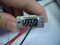
 Cablecons.jpg 600 × 382; 37 KB
 CalibImages.jpg 415 × 631; 108 KB
 Camera setup.png 958 × 572; 231 KB
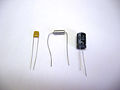 Capacior photo.jpg 800 × 600; 73 KB
- Capacitive touch controller.pdf ; 260 KB
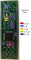 Capacitor chart.jpg 450 × 856; 89 KB
 Capacitor polarized symbol.gif 100 × 100; 466 bytes
 Capacitor symbol.gif 100 × 100; 416 bytes
 Capstone-gripper.png 1,646 × 902; 1.78 MB
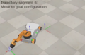
 Capstone-traj1.png 1,364 × 884; 755 KB
 Capstone-traj2.png 1,362 × 884; 768 KB
 Capstone-traj3.png 1,364 × 882; 726 KB
 Capstone-traj4.png 1,364 × 884; 764 KB
 Capstone-traj5.png 1,362 × 884; 800 KB
 Capstone-traj6.png 1,364 × 884; 763 KB
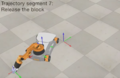 Capstone-traj7.png 1,362 × 882; 764 KB
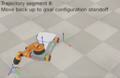 Capstone-traj8.png 1,364 × 884; 800 KB
 Carrier.jpg 400 × 340; 24 KB
- Cdc NTXPVista.inf ; 1 KB
 CentrifugalFanPicture.JPG 275 × 178; 29 KB
- Ch01.pdf ; 4.44 MB
- Ch02.pdf ; 2.94 MB
- Ch03.pdf ; 545 KB
- Ch04.pdf ; 286 KB
- Ch05.pdf ; 370 KB
- Ch06.pdf ; 21.63 MB
- Ch10 code.zip ; 1 KB
 Ch3 makefile.txt ; 1 KB
- Ch4 code.zip ; 3 KB
- Ch5 timing.c ; 563 bytes
- Ch6 code.zip ; 4 KB
- Ch7 code.zip ; 3 KB
- Ch8 code.zip ; 3 KB
- Ch9 code.zip ; 3 KB
- Chapter01-Quickstart-Jan2023.zip ; 20 KB
 Chasis.jpg 500 × 668; 105 KB
 ChasisUnderside.jpg 500 × 375; 77 KB
 Chip.gif 462 × 239; 19 KB
 Chladni 1speaker setup 704 × 528; 198 KB
 Chladni 339hz 422 × 317; 105 KB
 Chladni 3speaker base 704 × 528; 176 KB
 Chladni 3speaker setup 422 × 317; 76 KB
 Chladni 424hz 422 × 317; 106 KB
 Chladni 554hz 422 × 317; 105 KB
 Chladni 632hz 422 × 317; 102 KB
 Chladni 660hz 422 × 317; 103 KB
 Chladni 734hz 422 × 317; 102 KB
 Chladni UI box 704 × 528; 238 KB
 Chladni UI underside 704 × 528; 188 KB
 Chladni ad9833 adapter 704 × 528; 172 KB
 Chladni circuit actual 835 × 498; 202 KB
 Chladni circuit plugged 704 × 528; 348 KB
 Chladni circuit unplugged 704 × 528; 352 KB
- Chladni code.c ; 5 KB
 Chladni complete system 1,776 × 699; 289 KB
 Chladni la160 car amp 704 × 528; 211 KB
 Chladni plate 704 × 528; 137 KB
 Chladni speaker 704 × 528; 150 KB
 Chladni speaker bottom 704 × 528; 177 KB
 Chladni speaker cover 704 × 528; 127 KB
 Chladni tda2040 circuit 528 × 704; 214 KB
 Chladni team 410 × 274; 47 KB
 Chladni zeros circular plate 340 × 38; 8 KB
 Chladni zeros circular plate2 302 × 38; 7 KB
 Chladni zeros square plate 484 × 47; 12 KB
 Chladnis law 139 × 35; 3 KB
 Circle.jpg 1,006 × 732; 64 KB
 CircleGUI.jpg 1,366 × 768; 105 KB
 Circle very low gain.png 718 × 570; 35 KB
 Circuit.gif 350 × 351; 16 KB
- Circuit.tif 2,550 × 3,300; 285 KB
 CircuitBoard.jpg 1,280 × 960; 254 KB
 CircuitDiag.jpg 684 × 443; 26 KB
- CircuitMaker2000 manual.pdf ; 1.53 MB
 Circuit 2.GIF 256 × 203; 2 KB
 Circuit Diagram.jpg 753 × 594; 37 KB
 Circuit Photo Team22.jpg 3,072 × 2,304; 1.38 MB
 Circuit Top View.jpg 866 × 651; 109 KB
 Circuit diagram.bmp 395 × 294; 341 KB


