Uncategorized files
From Mech
Jump to navigationJump to searchShowing below up to 250 results in range #151 to #400.
View (previous 250 | next 250) (20 | 50 | 100 | 250 | 500)
 ACDC Jameco312864.pdf ; 284 KB
- ACS711.pdf ; 978 KB
- AD2S90.pdf ; 168 KB
- AD698.pdf ; 230 KB
- Error creating thumbnail: File missingAD9833Conn.jpg 343 × 345; 22 KB
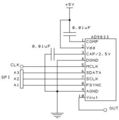 AD9833Connsmall.jpg 343 × 345; 22 KB
- ADA1103P.pdf ; 470 KB
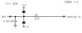 ADC.jpg 1,620 × 657; 35 KB
 ADC Read2.c ; 2 KB
- ADC Read2 LCD.c ; 2 KB
- ADC max rate.c ; 5 KB
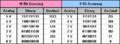 ADCvalues.JPG 483 × 177; 27 KB
- ADM3202-3.3V-RS232.pdf ; 333 KB
- ADXL362.pdf ; 898 KB
- AEAT-6600-T16.pdf ; 583 KB
- AEAT-9000-1GSH1.pdf ; 542 KB
- AN1388.pdf ; 511 KB
- AN1388B.pdf ; 463 KB
 AND gate symbol.gif 150 × 150; 516 bytes
 AO board.jpg 304 × 454; 33 KB
 AP KS GM=Control panel schematic.jpg 840 × 630; 50 KB
- ASM330LXH.pdf ; 1.04 MB
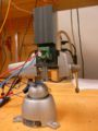
 Ac-servo-small.jpg 512 × 384; 73 KB
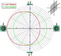
 AccelXY.JPG 526 × 478; 53 KB
 AccelXYwiki.jpg 496 × 478; 50 KB
 AccelXZ.JPG 537 × 510; 62 KB
 AccelXZwiki.JPG 536 × 510; 57 KB
 AccelYZ.JPG 559 × 483; 57 KB
 AccelYZwiki.JPG 521 × 483; 52 KB
 Accelerometer Rig.JPG 612 × 816; 77 KB
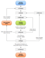 Activity lifecycle.png 513 × 663; 81 KB
 Adafruit RGB LEDS.jpg 970 × 728; 225 KB
 Add text.jpg 880 × 631; 148 KB
 Add trace.jpg 876 × 571; 98 KB
 Add via.jpg 882 × 630; 141 KB
 Advanced strain gauge attachment.jpg 492 × 358; 20 KB
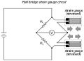 Advanced strain gauge circuit.jpg 482 × 355; 21 KB
 Advantechbot.jpg 640 × 480; 75 KB
 Advantechtop.jpg 640 × 480; 67 KB
 AirTableFlotationResults.jpg 1,095 × 196; 41 KB
 AjmDetector circuit.jpg 587 × 384; 56 KB
 All-actuators-captions-small.jpg 512 × 384; 96 KB
 Amp signal J1.jpg 385 × 203; 16 KB
 Amp signal J2.jpg 756 × 531; 60 KB
 Ampinput 1,024 × 768; 103 KB
 AmplifiedPT.gif 493 × 347; 4 KB
 Ampoutput 1,024 × 768; 324 KB
- AnalogDevices ADXL321EB.pdf ; 74 KB
 Analoginpic.gif 199 × 212; 1 KB
 Analoginputpot.gif 280 × 246; 1 KB
 Analyze Flexure GUI.png 1,267 × 716; 55 KB
 Android PIC starter code.zip ; 3.14 MB
 Angle vs output with room light.gif 483 × 288; 6 KB
 Angle vs output without room light.jpg 481 × 289; 6 KB
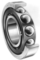 Angular ball bearing.png 175 × 264; 22 KB
 Angular ball bearing crosssection.gif 63 × 86; 1 KB
 Aninputckt.jpg 340 × 321; 24 KB
 ArchTeam22.jpg 500 × 890; 71 KB
 Artificial.jpg 344 × 335; 13 KB
 Asee 2016 iso.png 745 × 435; 350 KB
 Assembly.jpg 800 × 483; 77 KB
- Assignment1.zip ; 359 KB
- Assignment1Solutions.pdf ; 195 KB
- Assignment1Solutions.zip ; 6 KB
- Assignment2.pdf ; 181 KB
- Assignment2Solutions.pdf ; 103 KB
- Assignment2StudentSolutions.zip ; 183 KB
- Assignment3.pdf ; 185 KB
- Assignment3.zip ; 1.87 MB
- Assignment3Solutions.pdf ; 198 KB
- Assignment3Solutions.zip ; 189 KB
- Assignment3v2.pdf ; 185 KB
- Assignment4.zip ; 232 KB
- Assignment4Solutions.zip ; 220 KB
- Assignment4Solutionsv2.zip ; 194 KB
- Assignment5.zip ; 302 KB
- Assignment5Solutions.pdf ; 1 MB
- Assignment5Solutions.zip ; 111 KB
- Assignment5v2.zip ; 313 KB
- Assignment6.pdf ; 204 KB
- Assignment6.zip ; 630 KB
- Assignment7Solutions1.pdf ; 211 KB
- Assignment7Solutions2.pdf ; 382 KB
- Asst6-follow.pdf ; 1.15 MB
- Asst6.zip ; 204 KB
- Asst7.pdf ; 299 KB
 Astar-search.png 209 × 149; 62 KB
 AutomatedXylophoneCircuitDiagram.jpg 1,497 × 1,206; 210 KB
 AutomatedXylophoneGroup.jpg 800 × 600; 84 KB
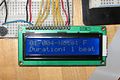 AutomatedXylophoneLCD.jpg 800 × 531; 116 KB
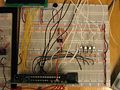 AutomatedXylophonePICCircuitry.jpg 800 × 600; 147 KB
 AutomatedXylophonePic2.jpg 800 × 600; 89 KB
 AutomatedXylophonePicture1.jpg 900 × 801; 120 KB
 AutomatedXylophoneRelays.jpg 800 × 600; 144 KB
 AutomatedXylophoneSolenoidInterface.jpg 800 × 600; 113 KB
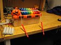
 AutomatedXylophoneSolenoids.jpg 800 × 600; 108 KB
 Automated Fish Refuge CloseupFish 1,600 × 1,200; 774 KB
 Automated fish refuge circuit.jpg 1,600 × 1,200; 878 KB
 Automated fish refuge closecircuit.jpg 628 × 490; 223 KB
 Automatic via.jpg 886 × 633; 105 KB
 AxialFanPicture.JPG 640 × 600; 96 KB
- B57164K.pdf ; 579 KB
- BKSBallControl.fig ; 7 KB
- BKSBallControl.m ; 22 KB
- BKSBallMasterv1.c ; 4 KB
- BKSBallSlave1v1.c ; 8 KB
- BKSBallSlavev1.c ; 8 KB
- BPI 216 Send v1.zip ; 12 KB
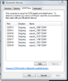 BT COM ports.png 385 × 460; 28 KB
 BallCaster.jpg 500 × 375; 63 KB
 Ballbalancechallenge.JPG 2,816 × 2,112; 2.5 MB
 Barrel.jpg 400 × 238; 17 KB
 Base.png 321 × 414; 189 KB
 Baseball Ball Sensor.jpg 1,052 × 900; 150 KB
 Baseball Base LED.jpg 903 × 777; 77 KB
 Baseball Bat.jpg 1,122 × 930; 108 KB
 Baseball LED circuitry.jpg 453 × 211; 17 KB
 Baseball PIC Circuitry.jpg 814 × 1,135; 155 KB
 Baseball Pitcher.jpg 1,268 × 948; 155 KB
 Baseball Playfield.jpg 1,264 × 952; 199 KB
 Baseball Recess.jpg 1,276 × 960; 174 KB
 Baseball Relay.jpg 944 × 1,115; 106 KB
 Baseball Scoreboard Circuitry.jpg 1,156 × 824; 181 KB
 Baseball Sensor.jpg 1,052 × 900; 150 KB
 Baseball Single.jpg 1,268 × 936; 96 KB
 Baseball array explanation.jpg 867 × 526; 54 KB
 Baseball array explanation2.jpg 896 × 526; 54 KB
- Baseball final.c ; 7 KB
- Baseball fullcode.c ; 7 KB
 Baseball pitcher bat circuitry.jpg 698 × 540; 27 KB
 Baseball sensor circuitry.jpg 672 × 394; 23 KB
 Basic model.jpg 228 × 42; 3 KB
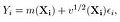
 Battery pack.jpg 400 × 300; 39 KB
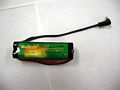
 Battery pack charger.jpg 400 × 300; 54 KB
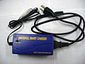
 BaudRate.vs.Latency.png 539 × 435; 30 KB
- Berard-Egan-Trinkle-ICRA2004.pdf ; 154 KB
- BerardTechReport.pdf ; 224 KB
 Bergquist hand ball balancing.jpg 216 × 222; 52 KB
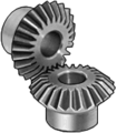 Bevel gears.png 154 × 176; 12 KB
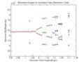 BifDiag Small.jpg 560 × 420; 26 KB
 Binary.jpg 422 × 372; 22 KB
 Bipolar.gif 338 × 158; 2 KB
 Bipolar2input.png 360 × 200; 1 KB
 Bipolar4input.png 516 × 398; 2 KB
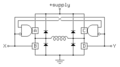
 Bipolar Stepper Motor Drive Circuit JSJW.JPG 1,189 × 697; 56 KB
 Bipolaranim.gif 340 × 159; 36 KB
 Bipolarstepper.gif 338 × 158; 2 KB
 Bipwmckt.jpg 470 × 272; 24 KB
- Bix-IMECE2016.pdf ; 13.67 MB
 Block-capstone.png 1,336 × 1,138; 138 KB
- Blockdiag.jpg 740 × 436; 98 KB
 Blown-up-battery.jpg 1,035 × 630; 217 KB
- BoB partslist 526 2005-12-14.xls ; 30 KB
- BoB partslist 526 2005-12-28.xls ; 30 KB
 Board size.jpg 708 × 584; 59 KB
 Bobbot.jpg 2,048 × 1,536; 377 KB
 Bobtop.jpg 2,048 × 1,536; 417 KB
 Bode plots 1.bmp 834 × 713; 583 KB
 Bode plots 1.jpg 835 × 713; 64 KB
- Book-current.pdf ; 38.76 MB
- Book-draft-April1-2015.pdf ; 64.21 MB
- Boot600.zip ; 641 KB
- Bootloader.zip ; 119 KB
- Bouncing Ball Simulator.zip ; 5 KB
 Bouncing switch.jpg 372 × 276; 40 KB
 Box.png 912 × 608; 795 KB
 Bpgain.jpg 376 × 221; 17 KB
 Bps-nrf24l01.jpg 560 × 420; 31 KB
- Brass cylinder.zip ; 20 KB
 Breadboard ac adapter.jpg 400 × 300; 51 KB
 Breadboard large.jpg 400 × 300; 68 KB
 Breadboard small.jpg 400 × 300; 61 KB
 BuiltChasis.jpg 500 × 375; 67 KB
 BuiltChasis2 MLS.jpg 2,304 × 1,728; 1.78 MB
 ButterflyCircuitDiagram.jpg 1,240 × 958; 234 KB
 ButterflyCircuitDiagram2.jpg 1,145 × 859; 79 KB
 ButterflyCircuitDiagram3.jpg 1,145 × 859; 80 KB
- ButterflyFinalCode.zip ; 113 KB
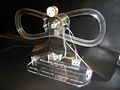
 Butterfly Circuit.jpg 448 × 309; 78 KB
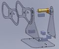 Butterfly Exploded View.jpg 915 × 768; 63 KB
- Butterfly Matlab code.zip ; 57 KB
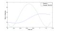 Butterfly Trajectory.jpg 1,280 × 682; 46 KB
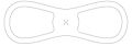 Butterfly shape.jpg 448 × 156; 14 KB
 Butterflyteampic.jpg 448 × 336; 32 KB
 Bypass cap.gif 318 × 165; 1 KB
 ByteSize.Vs.latency.png 616 × 512; 39 KB
 C18 tutorial ADC breadboard.jpeg 2,304 × 1,728; 1.76 MB
 C18 tutorial ADC wiring.gif 608 × 395; 19 KB
- C18 tutorial ADC wiring.ppt ; 47 KB
 C18 tutorial Motor controller DE9F.jpeg 1,600 × 1,200; 949 KB
 C18 tutorial Motor controller wiring.gif 925 × 680; 43 KB
 C18 tutorial add files.gif 296 × 403; 11 KB
 C18 tutorial hyperterminal choose baud.png 361 × 427; 22 KB
 C18 tutorial hyperterminal choose emulation.png 353 × 430; 28 KB
 C18 tutorial hyperterminal choose name.png 363 × 323; 15 KB
 C18 tutorial hyperterminal choose port.png 309 × 314; 12 KB
 C18 tutorial hyperterminal open.png 671 × 566; 180 KB
 C18 tutorial motor controller breadboard.jpeg 2,304 × 1,728; 1.76 MB
 C18 tutorial welcome message.png 646 × 351; 21 KB
- CBook.pdf ; 3.49 MB
- CCCHelloWorld.c ; 79 bytes
- CCCbubble.c ; 641 bytes
- CCCdatasizes.c ; 754 bytes
- CCChelper.c ; 335 bytes
 CCChelper.h ; 355 bytes
- CCChexdump.c ; 1 KB
- CCCinvest.c ; 5 KB
- CCClights.c ; 1 KB
- CCCmain.c ; 295 bytes
- CCCoverflow.c ; 421 bytes
- CCCprintout.c ; 298 bytes
- CCCtypecast.c ; 497 bytes
 CM AC sweep graph.png 990 × 692; 56 KB
 CM AC sweep setup.png 528 × 268; 15 KB
 CM DC sweep 1src graph.png 1,017 × 699; 39 KB
 CM DC sweep 1src setup.png 445 × 318; 14 KB
 CM DC sweep 2src.png 1,012 × 278; 9 KB
 CM DC sweep ciruict.gif 374 × 232; 2 KB
 CM LPF circuit.gif 294 × 193; 1 KB
 CM LPF graph.png 1,018 × 694; 40 KB
 CM LPF graph2.png 1,017 × 279; 10 KB
 CM RC circuit.gif 252 × 216; 1 KB
 CM RC discharge.gif 144 × 172; 678 bytes
 CM RC dishcarge IC.gif 188 × 166; 890 bytes
 CM RC exponential1.jpg 1,020 × 704; 155 KB
 CM add parts.jpg 290 × 184; 33 KB
 CM analog button.gif 104 × 26; 535 bytes
 CM capacitor IC graph.jpg 1,024 × 700; 143 KB
 CM capacitor IC set.jpg 336 × 431; 60 KB
 CM connected circuit.gif 160 × 219; 950 bytes
 CM digital mode button.gif 104 × 26; 485 bytes
 CM disconnected circuit.gif 184 × 165; 688 bytes
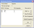 CM edit pin data.jpg 375 × 313; 45 KB
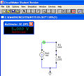 CM multimeter.jpg 444 × 400; 70 KB
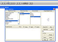 CM part menu.jpg 728 × 530; 102 KB
 CM pin numbers.gif 317 × 270; 2 KB
 CM probe tool.gif 26 × 23; 139 bytes
 CM run button.gif 26 × 23; 148 bytes
 CM wiretool.gif 26 × 23; 124 bytes
 CPAddInv.png 520 × 408; 37 KB
 CPAddedAll.png 522 × 410; 39 KB
 CPBrwsDir.png 576 × 461; 47 KB
 CPBrwsRslt.png 515 × 405; 46 KB
 CPPICSelDrDwnMnu.png 1,024 × 768; 84 KB


