Difference between revisions of "Setup, Use, and Modeling of Harmonic Drive Motors with Junus Amps"
Philip Dames (talk | contribs) |
Philip Dames (talk | contribs) |
||
| Line 25: | Line 25: | ||
** 100% mode - In addition to the PWM input pin there is an extra input pin (pin 4) to control the sign (or direction) of the output. Here, a 0% duty cycle is the zero point, 100% duty cycle with the direction pin LO is fully negative and 100% duty cycle with the direction pin HI is fully positive. |
** 100% mode - In addition to the PWM input pin there is an extra input pin (pin 4) to control the sign (or direction) of the output. Here, a 0% duty cycle is the zero point, 100% duty cycle with the direction pin LO is fully negative and 100% duty cycle with the direction pin HI is fully positive. |
||
<br clear=all> |
<br clear=all> |
||
Now click on the Motor button in the block diagram. Here you can input all the necessary parameters about your motor from the data sheet, or that you experimentally found. Now you are ready to look at the control loop. There is a PI controller with tunable parameters used to control the output current. While you are welcome to play around with the parameters on your own, I would suggest that you click on the I Loop button and select Auto Tune, at least to get a starting point for the parameters. It will give you several options based on different levels of aggressiveness of the controller. |
|||
Click on Input/Output. Here you can set up the different input and output pins. I recommend using IN1 as Amp Enable-HI (or LO) Enables With Clear Faults (pin 13). This ensures that the motor can only spin when you give it a command to turn on. Choose HI if your digital outputs default to LO, or vice versa, as it can vary depending on the presence of pull-up resistors, etc. You now have your amp configured and you are ready to start controlling your motor. |
|||
There are also a couple of other utilities built into the CME2 software. The first is the Control Panel (second button from the left in the top menu). This allows you to software enable/disable the amplifier as well as monitor various inputs/outputs of the motor during use. The other is the Scope (third button from the left in the top menu). This lets you apply various functions to drive the motor and monitor inputs/outputs over time. This is useful for making sure your control parameters are tuned the way you like them. |
|||
= Using the Motor = |
|||
If you are using analog command mode, a simple test to make sure your setup is working correctly is to connect the enable pin to +5V (or GND, depending on how it was configured) and use a potentiometer to control the input voltage and make sure the motor spins as you would expect it to. As a reminder, 0V is 0 output, negative voltage will move it in one direction and positive voltage in the other. |
|||
If you are using PWM command mode, a more involved test would be to do the activity found [[ME 333 Lab 4 | here]]. For our system, the plant would be the entire amp/motor package and feedback loop in the diagram at the top is designed to control the position of the motor. |
|||
= Motor Modeling = |
|||
For our purposes, we have chosen to model the motor using the following equation, where <math>\tau</math> is the output torque, <math>k_m</math> is the motor constant, <math>i</math> is the command current, <math>\mu_d</math> is the dynamic friction coefficient, <math>mu_s</math> is the static friction, <math>\omega</math> is the speed of the motor, and the <math>sgn</math> function returns the sign of its argument. |
|||
<math> \tau = k_m i - \mu_d \omega - \mu_s sgn(\omega) \,</math> |
|||
This can be easily solved to find the necessary command current (and thus the analog or PWM input) needed to follow a reference trajectory, which would be the feedforward model of our system. |
|||
To determine the values of the parameters in the above equation, you must run a series of tests at various input levels (at least 3, but more are recommended to make sure the parameters are constant at various speeds and accelerations of the motor). To set up the experiment you will need a mount for the motor (a table-mount vice works well), an object of known inertia (ex. momentum wheel), and you will need to hook up the encoder on the motor to a device that can read it in. |
|||
Revision as of 13:43, 4 September 2010
Setting up the Junus Amplifier
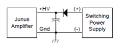
The first thing you need to run the amplifier is to find a DC power source that outputs 20-90V with a maximum current greater than what you expect your motor(s) to draw. This should be connected to the amplifier according to the following diagram, where the capacitors and diodes are rated for the voltages/currents you are expecting to see.
Next, use the USB to RS-232 cable to connect the amp to your PC. If this doesn't work you will need to find and install the driver for the HL-340 USB to serial converter (there is a copy of the driver in the folder Philip's Files\usb-serial-driver.zip on the desktop of the PC used for the QNX manipulation project). You will also need to download and install CME2 (Copley Motion Explorer); note that Copley's documentation for the amplifier and software can also be downloaded from the same page.
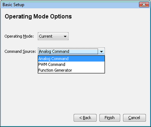
Open the program and add the COM port used by the USB to serial cable to the list (the list can be changed later in the Tools -> Communication Wizard menu). Next go to Amplifier -> Basic Setup. Here you select from the different operational modes and input types.
Operating Modes
- Current - This is the most commonly used mode. Here, the amplifier will create an output current proportional to some input signal to drive the attached actuator. In this mode there is only one control loop running within the amplifier making it the preferred choice (the more control that can be done outside the amp, the less of a black box it is).
- Velocity - This mode takes the current control mode and adds another feedback loop around the current control loop so that the velocity of the motor is proportional to the input signal. For the Junus amps, the motor speed is estimated from the back emf of the motor during use, making it less reliable than the current control mode.
Command Sources
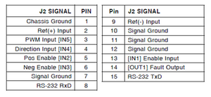
The pin diagram for the Junus amp is found to the right.
- Analog Command - In this mode, an analog input is connected to pins 2 and 9, with the analog reference voltage going to pin 9 and the signal going to pin 2. The voltage range for the input is +/- 10V with the output being proportional to the voltage, i.e. 0V is 0A (or 0rpm) output, +10V is maximum positive current output, and -10V is maximum negative current output.
- PWM Command - In this mode the output is related to the duty cycle of the PWM signal in one of two ways. To switch between these modes, click on the PWM command button in the block diagram.
- 50% mode - This mode uses a single input pin (pin 3). Here a 50% duty cycle is the zero point (0A or 0rpm) with 0% being fully negative and 100% being fully positive.
- 100% mode - In addition to the PWM input pin there is an extra input pin (pin 4) to control the sign (or direction) of the output. Here, a 0% duty cycle is the zero point, 100% duty cycle with the direction pin LO is fully negative and 100% duty cycle with the direction pin HI is fully positive.
Now click on the Motor button in the block diagram. Here you can input all the necessary parameters about your motor from the data sheet, or that you experimentally found. Now you are ready to look at the control loop. There is a PI controller with tunable parameters used to control the output current. While you are welcome to play around with the parameters on your own, I would suggest that you click on the I Loop button and select Auto Tune, at least to get a starting point for the parameters. It will give you several options based on different levels of aggressiveness of the controller.
Click on Input/Output. Here you can set up the different input and output pins. I recommend using IN1 as Amp Enable-HI (or LO) Enables With Clear Faults (pin 13). This ensures that the motor can only spin when you give it a command to turn on. Choose HI if your digital outputs default to LO, or vice versa, as it can vary depending on the presence of pull-up resistors, etc. You now have your amp configured and you are ready to start controlling your motor.
There are also a couple of other utilities built into the CME2 software. The first is the Control Panel (second button from the left in the top menu). This allows you to software enable/disable the amplifier as well as monitor various inputs/outputs of the motor during use. The other is the Scope (third button from the left in the top menu). This lets you apply various functions to drive the motor and monitor inputs/outputs over time. This is useful for making sure your control parameters are tuned the way you like them.
Using the Motor
If you are using analog command mode, a simple test to make sure your setup is working correctly is to connect the enable pin to +5V (or GND, depending on how it was configured) and use a potentiometer to control the input voltage and make sure the motor spins as you would expect it to. As a reminder, 0V is 0 output, negative voltage will move it in one direction and positive voltage in the other.
If you are using PWM command mode, a more involved test would be to do the activity found here. For our system, the plant would be the entire amp/motor package and feedback loop in the diagram at the top is designed to control the position of the motor.
Motor Modeling
For our purposes, we have chosen to model the motor using the following equation, where is the output torque, is the motor constant, is the command current, is the dynamic friction coefficient, is the static friction, is the speed of the motor, and the function returns the sign of its argument.
This can be easily solved to find the necessary command current (and thus the analog or PWM input) needed to follow a reference trajectory, which would be the feedforward model of our system.
To determine the values of the parameters in the above equation, you must run a series of tests at various input levels (at least 3, but more are recommended to make sure the parameters are constant at various speeds and accelerations of the motor). To set up the experiment you will need a mount for the motor (a table-mount vice works well), an object of known inertia (ex. momentum wheel), and you will need to hook up the encoder on the motor to a device that can read it in.


