Difference between revisions of "Setup, Use, and Modeling of Harmonic Drive Motors with Junus Amps"
Philip Dames (talk | contribs) |
Philip Dames (talk | contribs) |
||
| Line 1: | Line 1: | ||
= Setting up the Junus Amplifier = |
= Setting up the Junus Amplifier = |
||
[[Image:power_supply_diagram.png|thumb |
[[Image:power_supply_diagram.png|thumb|Power Supply Diagram|right]] |
||
The first thing you need to run the amplifier is to find a DC power source that outputs 20-90V with a maximum current greater than what you expect your motor(s) to draw. This should be connected to the amplifier according to the following diagram, where the capacitors and diodes are rated for the voltages/currents you are expecting to see. |
The first thing you need to run the amplifier is to find a DC power source that outputs 20-90V with a maximum current greater than what you expect your motor(s) to draw. This should be connected to the amplifier according to the following diagram, where the capacitors and diodes are rated for the voltages/currents you are expecting to see. |
||
<br clear=all> |
|||
Next, use the USB to RS-232 cable to connect the amp to your PC. If this doesn't work you will need to find and install the driver for the HL-340 USB to serial converter (there is a copy of the driver in the folder Philip's Files\usb-serial-driver.zip on the desktop of the PC used for the QNX manipulation project). You will also need to download and install [http://www.copleycontrols.com/Motion/Downloads/index.html CME2] (Copley Motion Explorer); note that Copley's documentation for the amplifier and software can also be downloaded from the same page. |
|||
<br clear=all> |
|||
[[Image:copley_basic_setup.png|thumb|Basic Setup Menu|right]] |
|||
Open the program and add the COM port used by the USB to serial cable to the list (the list can be changed later in the Tools -> Communication Wizard menu). Next go to Amplifier -> Basic Setup. Here you select from the different operational modes and input types. |
|||
<br clear=all> |
|||
== Operating Modes == |
|||
* Current - This is the most commonly used mode. Here, the amplifier will create an output current proportional to some input signal to drive the attached actuator. In this mode there is only one control loop running within the amplifier making it the preferred choice (the more control that can be done outside the amp, the less of a black box it is). |
|||
* Velocity - This mode takes the current control mode and adds another feedback loop around the current control loop so that the velocity of the motor is proportional to the input signal. For the Junus amps, the motor speed is estimated from the back emf of the motor during use, making it less reliable than the current control mode. |
|||
== Command Sources == |
|||
<br clear=all> |
|||
[[Image:junus_amp_pin_diagram.png|thumb|Junus Amp Input Pin Diagram|right]] |
|||
The pin diagram for the Junus amp is found to the right. |
|||
* Analog Command - In this mode, an analog input is connected to pins 2 and 9, with the analog reference voltage going to pin 9 and the signal going to pin 2. The voltage range for the input is +/- 10V with the output being proportional to the voltage, i.e. 0V is 0A (or 0rpm) output, +10V is maximum positive current output, and -10V is maximum negative current output. |
|||
* PWM Command - In this mode the output is related to the duty cycle of the PWM signal in one of two ways. To switch between these modes, click on the PWM command button in the block diagram. |
|||
** 50% mode - This mode uses a single input pin (pin 3). Here a 50% duty cycle is the zero point (0A or 0rpm) with 0% being fully negative and 100% being fully positive. |
|||
** 100% mode - In addition to the PWM input pin there is an extra input pin (pin 4) to control the sign (or direction) of the output. Here, a 0% duty cycle is the zero point, 100% duty cycle with the direction pin LO is fully negative and 100% duty cycle with the direction pin HI is fully positive. |
|||
<br clear=all> |
<br clear=all> |
||
Revision as of 12:42, 4 September 2010
Setting up the Junus Amplifier
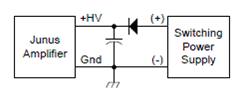
The first thing you need to run the amplifier is to find a DC power source that outputs 20-90V with a maximum current greater than what you expect your motor(s) to draw. This should be connected to the amplifier according to the following diagram, where the capacitors and diodes are rated for the voltages/currents you are expecting to see.
Next, use the USB to RS-232 cable to connect the amp to your PC. If this doesn't work you will need to find and install the driver for the HL-340 USB to serial converter (there is a copy of the driver in the folder Philip's Files\usb-serial-driver.zip on the desktop of the PC used for the QNX manipulation project). You will also need to download and install CME2 (Copley Motion Explorer); note that Copley's documentation for the amplifier and software can also be downloaded from the same page.
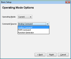
Open the program and add the COM port used by the USB to serial cable to the list (the list can be changed later in the Tools -> Communication Wizard menu). Next go to Amplifier -> Basic Setup. Here you select from the different operational modes and input types.
Operating Modes
- Current - This is the most commonly used mode. Here, the amplifier will create an output current proportional to some input signal to drive the attached actuator. In this mode there is only one control loop running within the amplifier making it the preferred choice (the more control that can be done outside the amp, the less of a black box it is).
- Velocity - This mode takes the current control mode and adds another feedback loop around the current control loop so that the velocity of the motor is proportional to the input signal. For the Junus amps, the motor speed is estimated from the back emf of the motor during use, making it less reliable than the current control mode.
Command Sources
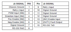
The pin diagram for the Junus amp is found to the right.
- Analog Command - In this mode, an analog input is connected to pins 2 and 9, with the analog reference voltage going to pin 9 and the signal going to pin 2. The voltage range for the input is +/- 10V with the output being proportional to the voltage, i.e. 0V is 0A (or 0rpm) output, +10V is maximum positive current output, and -10V is maximum negative current output.
- PWM Command - In this mode the output is related to the duty cycle of the PWM signal in one of two ways. To switch between these modes, click on the PWM command button in the block diagram.
- 50% mode - This mode uses a single input pin (pin 3). Here a 50% duty cycle is the zero point (0A or 0rpm) with 0% being fully negative and 100% being fully positive.
- 100% mode - In addition to the PWM input pin there is an extra input pin (pin 4) to control the sign (or direction) of the output. Here, a 0% duty cycle is the zero point, 100% duty cycle with the direction pin LO is fully negative and 100% duty cycle with the direction pin HI is fully positive.


