Difference between revisions of "Rotary Encoder"
| Line 308: | Line 308: | ||
binary bit is the exlcusive OR (XOR) combination of adjacent gray |
binary bit is the exlcusive OR (XOR) combination of adjacent gray |
||
code bits. |
code bits. |
||
293835705943398248937778 |
|||
<h4>Incremental encoder</h4> |
<h4>Incremental encoder</h4> |
||
Revision as of 05:52, 27 November 2006
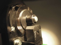
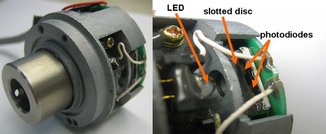
A digital optical encoder is a device that converts motion into a sequence of digital pulses. By counting a single bit or by decoding a set of bits, the pulses can be converted to relative or absolute position measurements. Encoders have both linear and rotary configurations, but the most common type is rotary. Rotary encoders are manufactured in two basic forms: 1) the absolute encoder where a unique digital word corresponds to each rotational position of the shaft, and 2) the incremental encoder, which produces digital pulses as the shaft rotates, allowing measurement of relative position of shaft. Most rotary encoders are composed of a glass or plastic slotted disk. As radial lines in each track interrupt the beam between a photoemitter-detector pair (or Optointerrupter), digital pulses are produced.
Absolute encoder
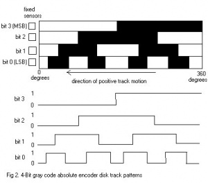
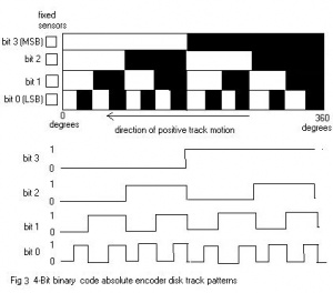
The optical disk of the absolute encoder is designed to produce a digital word that distinguishes N distinct positions of the shaft. For example, if there are 8 tracks, the encoder is capable of producing 256 distinct positions or an angular resolution of 1.406 (360/256) degrees. The most common types of numerical encoding used in the absolute encoder are gray and binary codes. To illustrate the acion of an absolute encoder, the gray code and natural binary code dsisk track patterns for a simple 4-track (4-bit) encoder are illustrated in Fig 2 and 3. The linear patterns and associated timing diagrams are what the photodetectors sense as the code disk circular tracks rotate with the shaft. The output bit codes for both coding schemes are listed in Table 1.
 |
|
|
Decimal code |
Rotation range (deg.) |
Binary code |
Gray code |
|
0 |
0-22.5 |
0000 |
0000 |
|
1 |
22.5-45 |
0001 |
0001 |
|
2 |
45-67.5 |
0010 |
0011 |
|
3 |
67.5-90 |
0011 |
0010 |
|
4 |
90-112.5 |
0100 |
0110 |
|
5 |
112.5-135 |
0101 |
0111 |
|
6 |
135-157.5 |
0110 |
0101 |
|
7 |
15.75-180 |
0111 |
0100 |
|
8 |
180-202.5 |
1000 |
1100 |
|
9 |
202.5-225 |
1001 |
1101 |
|
10 |
225-247.5 |
1010 |
1111 |
|
11 |
247.5-270 |
1011 |
1110 |
|
12 |
270-292.5 |
1100 |
1010 |
|
13 |
292.5-315 |
1101 |
1011 |
|
14 |
315-337.5 |
1110 |
1001 |
|
15 |
337.5-360 |
1111 |
1000 |
Table 1. 4-Bit gray and natural binary codes
The gray code is designed so that only one track (one bit) will change state for each count transition, unlike the binary code where multiple tracks (bits) change at certain count transitions. This effect can be seen clearly in Table 1. For the gray code, the uncertainty during a transition is only one count, unlike with the binary code, where the uncertainty could be multiple counts.
Since the gray code provides data with the least uncertainty but the natural binary code is the preferred choice for direct interface to computers and other digital devices, a circuit to convert from gray to binary code is desirable. Figure 4 shows a simple circuit that utilizes exclusive OR gates (XOR) to perform this function.For a gray code to binary code conversion of any number of bits N, the most signficant bits (MSB) of the binary and gray code are always identical, and for each other bit, the binary bit is the exlcusive OR (XOR) combination of adjacent gray code bits. 293835705943398248937778
Incremental encoder
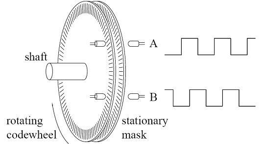
The incremental encoder, sometimes called a relative encoder, is simpler in design than the absolute encoder. It consists of two tracks and two sensors whose outputs are called channels A and B. As the shaft rotates, pulse trains occur on these channels at a frequency proportional to the shaft speed, and the phase relationship between the signals yields the direction of rotation. The code disk pattern and output signals A and B are illustrated in Figure 5. By counting the number of pulses and knowing the resolution of the disk, the angular motion can be measured. The A and B channels are used to determine the direction of rotation by assessing which channels "leads" the other. The signals from the two channels are a 1/4 cycle out of phase with each other and are known as quadrature signals. Often a third output channel, called INDEX, yields one pulse per revolution, which is useful in counting full revolutions. It is also useful as a reference to define a home base or zero position.
Figure 5 illustrates two separate tracks for the A and B channels, but a more common configuration uses a single track with the A and B sensors offset a 1/4 cycle on the track to yield the same signal pattern. A single-track code disk is simpler and cheaper to manufacture.
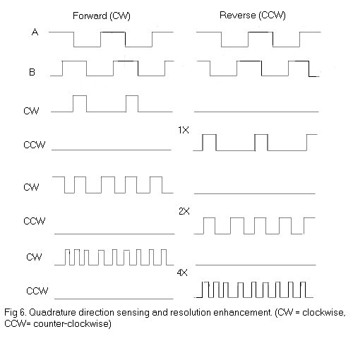
The quadrature signals A and B can be decoded to yield the direction of rotation as hown in Figure 6. Decoding transitions of A and B by using sequential logic circuits in different ways can provide three different resolutions of the output pulses: 1X, 2X, 4X. 1X resolution only provides a single pulse for each cycle in one of the signals A or B, 4X resolution provides a pulse at every edge transition in the two signals A and B providing four times the 1X resolution. The direction of rotation(clockwise or counter-clockwise) is determined by the level of one signal during an edge transition of the second signal. For example, in the 1X mode, A= with B =1 implies a clockwise pulse, and B= with A=1 implies a counter-clockwise pulse. If we only had a single output channel A or B, it would be impossible to determine the direction of rotation. Furthermore, shaft jitter around an edge transition in the single signal woudl result in erroneous pulses..
Connecting an Encoder to the PC/104 Stack
To connect an encoder to the PC/104 stack, you will have to create a suitable ribbon cable connector. The connector that came with the encoder will most likely not match the correct pinout to attach. Consult the PC104 I/O page to see how to connect the encoder.
Datasheets
Datasheet for the Maxon Tacho 103935 encoder: Media:maxon_tacho_103935_encoder.pdf
References
Introduction to Mechatronics and Measurement Systems, Histand & Alciatore, 1999 McGraw Hill
