Difference between revisions of "Robot Drummer"
(→Set Up) |
(→Set Up) |
||
| Line 34: | Line 34: | ||
<b>H-Bridge</b> |
<b>H-Bridge</b> |
||
The slave PICs send an individual [[Pulse_width_modulation|PWM]] to an L293D H-bridge. This PWM determines the speed of each motor. The motor is at rest at a 50% duty cycle and is at its maximum speed at 0 and 100% duty cycles. Pin 16 of the slave PICs connect to pin 2 of the L293D. |
The slave PICs send an individual [[Pulse_width_modulation|PWM]] to an L293D H-bridge. This PWM determines the speed of each motor. The motor is at rest at a 50% duty cycle and is at its maximum speed at 0 and 100% duty cycles. Pin 16 of the slave PICs connect to pin 2 of the L293D. |
||
<b>Hex Inverter</b> |
<b>Hex Inverter</b> |
||
Pin 16 of the slave PICs is also run through a the hex inverter chip. The output of the hex inverter (pin 2 or pin 12) is sent to pin 7 of the L293D. |
Pin 16 of the slave PICs is also run through a the hex inverter chip. The output of the hex inverter (pin 2 or pin 12) is sent to pin 7 of the L293D. |
||
Revision as of 22:38, 12 March 2009
Team Members
- Bobby By: Senior in Electrical Engineering
- Agatha Lee: Master Student in Biomedical Engineering
- Dan Niecestro: Senior in Mechanical Engineering
Overview
This project consisted of creating motor control PICs that will make it easy for anyone to do high-speed encoder-based feedback control of brushed DC motors with only a few dollars of hardware and a cable to connect to Matlab on a PC. The "master" PIC commnicates with the PC and any number of "slave" PICs, two in our case. The master PIC takes the takes program written in Matlab and communicates it to the slave PICs and to coordinate the initiation of moves by the slave PICs. To demonstrate motor control, a drumming device was created.
Mechanical Set-Up
Circuitry
Component List
| Part | Part No. | Qty |
|---|---|---|
| PIC18F4520 Prototyping Board | --- | 3 |
| Microchip 8-bit PIC Microcontroller | PIC18F4520 | 1 |
| Microchip 8-bit PIC Microcontroller | PIC18F4431 | 2 |
| Pittman Motor with Encoder | GM8224 | 2 |
| Hex Inverter Chip | SN74HC04 | 1 |
| H-Bridge Chip | L293D | 2 |
| 10K Resistor | --- | 2 |
Set Up
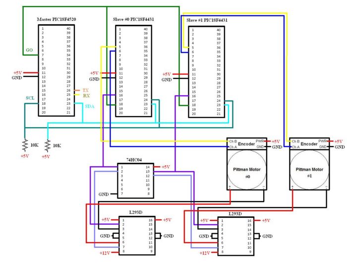
All of the components, except the Pittman motors, were powered with 5V DC. The Pittman motors were powered with 12V DC.
PICs
The PICs used were one "master" 18F4520 and two "slaves" 18F4431. The three PICs communicated via I2C, which enabled us to control the two motors by telling the master PIC what to do through Matlab.
H-Bridge
The slave PICs send an individual PWM to an L293D H-bridge. This PWM determines the speed of each motor. The motor is at rest at a 50% duty cycle and is at its maximum speed at 0 and 100% duty cycles. Pin 16 of the slave PICs connect to pin 2 of the L293D.
Hex Inverter
Pin 16 of the slave PICs is also run through a the hex inverter chip. The output of the hex inverter (pin 2 or pin 12) is sent to pin 7 of the L293D.
Schematic

