Difference between revisions of "PIC MCUs: Hardware and Connections"
From Mech
Jump to navigationJump to search| Line 1: | Line 1: | ||
The ICD-U40 programmer/debugger connects to the CCS Windows IDE via the USB port of your computer, and connects to the PIC microcontroller through a modular cable. Although the boards provided for |
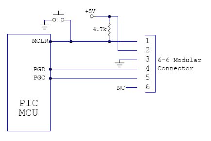
The ICD-U40 programmer/debugger connects to the CCS Windows IDE via the USB port of your computer, and connects to the PIC microcontroller through a modular cable. Although the boards provided for ME 233/333/433 and in the lab are already wired correctly, a wiring diagram for communication with the PIC microcontroller is given below for reference. |
||
[[Image:comm.jpg]] |
[[Image:comm.jpg]] |
||
<br> |
<br> |
||
Revision as of 14:41, 25 June 2007
The ICD-U40 programmer/debugger connects to the CCS Windows IDE via the USB port of your computer, and connects to the PIC microcontroller through a modular cable. Although the boards provided for ME 233/333/433 and in the lab are already wired correctly, a wiring diagram for communication with the PIC microcontroller is given below for reference.

While the ICD is connected to the PIC MCU and to your computer via a USB cable the Windows IDE will be able to communicate with the PIC microcontroller. In order to program or debug successfully, these connections must be made correctly.