Difference between revisions of "PIC18F4520: Digital Inputs"
m |
|||
| Line 53: | Line 53: | ||
===Circuit Diagram=== |
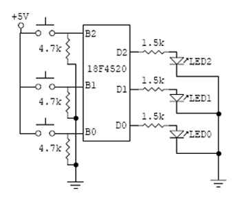
===Circuit Diagram=== |
||
[[Image: |
[[Image:Digitalinckt.jpg]] |
||
Revision as of 13:45, 29 June 2007
Available Pins
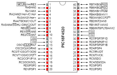
With the exception of the positive voltage supply and ground pins, all pins on the PIC18F4520 can be used as digital I/O, however a few other pins (shown in grey below) are commonly utilized for communication instead of digital I/O.
Digital Inputs Example
Sample Code
Program to display push-button input as LED output
First include header file with definitions for specific PIC. Set fuses. HS is type of external clock, low voltage protection (LVP) is off, and the watchdog timer (WDT) is off. External clock frequency of 20 MHz is specified.
  #include <18f4520.h>
  #fuses HS,NOLVP,NOWDT
  #use delay (clock=20000000)
Define pin names to be used in the main program. See header file for currently defined pin names.
  #define IN0 PIN_B0
  #define IN1 PIN_B1
  #define IN2 PIN_B2
  #define OUT0 PIN_D0
  #define OUT1 PIN_D1
  #define OUT2 PIN_D2
Begin main body of program.
void main(void) {
Use while to set up infinite loop.
while(TRUE){
Check each input pin and define action to be taken depending on reading from input (in this case, set the output to the input).
        if(input(IN0))
           output_high(OUT0);
        else if (!input(IN0))
           output_low(OUT0);
        if(input(IN1))
           output_high(OUT1);
        else if (!input(IN1))
           output_low(OUT1);
        if(input(IN2))
           output_high(OUT2);
        else if (!input(IN2))
           output_low(OUT2);}
  }

