PIC16F684
From Mech
The printable version is no longer supported and may have rendering errors. Please update your browser bookmarks and please use the default browser print function instead.
Overview
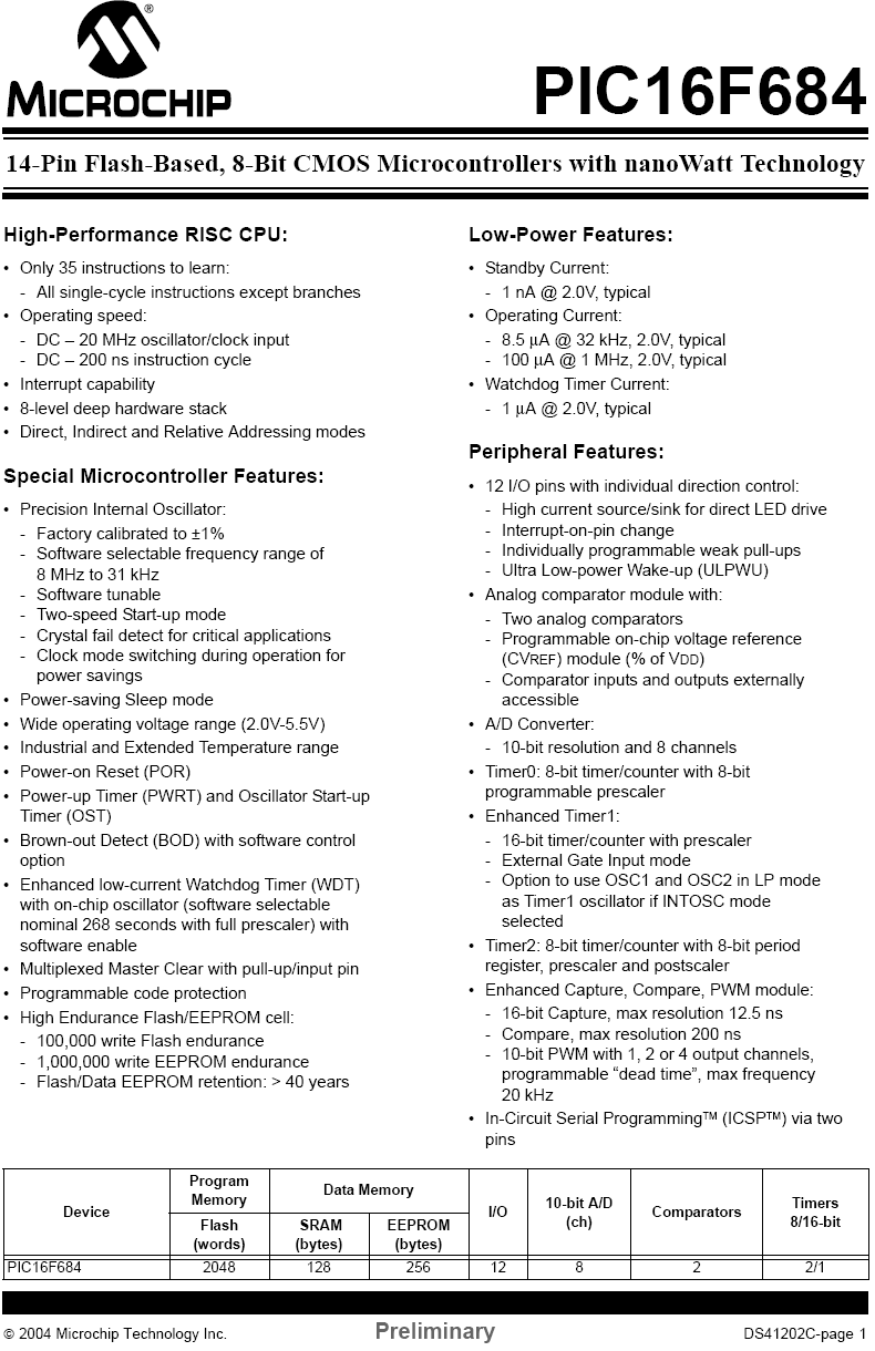
For a complete list of features, see this printout from the datasheet.
IMPORTANT: See PIC16F684 Registers for detailed information on registers.
Pinout

| Label | Description |
|---|---|
| + 5 V | |
| Ground | |
| External Voltage Reference | |
| PORTA/PORTC Programmable I/O | |
| A/D Channel | |
| External Interrupt Input | |
| PWM Output |


Initialization
Configuring I/O
This section shows two sections of code that are used for setting up the I/O of the PIC. The INIT_IO function sets up the ports by setting their default value and their direction. The second function, INIT_ADC sets up the A/D converter.
INIT_IO
	BCF 		STATUS,RP0 		;Bank 0
	CLRF 		PORTA 			;Init PORTA - initially set to LOW
	MOVLW 	B'000101'			;Set RA<0> as input
	MOVWF 		TRISA 			;	and set RA<5:1>
						;	as outputs

	BSF 		STATUS,RP0 		;Bank 1
	CLRF 		PORTC 			;Init PORTC - initially set to LOW
	MOVLW 	B'000000'			;Set RC<5:0> as outputs
	MOVWF 		TRISC

	CLRF		ANSEL			;Set all pins initially to digital I/O
	MOVLW	B'000001'
	MOVWF		ANSEL			;Set AN<0> (RA<0>) to Analog input
						;	RA<5:1> remain digital I/O
	RETURN

INIT_ADC
	BCF 		STATUS,RP0 		;Bank 0
        MOVLW   B'00000001'			; Set output to left justified
	MOVWF   	ADCON0			; Select AN<0> (RA<0>) as input
						; Internal Vref
						; Start ADC ON

	BSF 		STATUS,RP0 		;Bank 1
	CLRF		ADCON1
        MOVLW   B'00100000' 		        ;Set Clock TAD to 1.6us (Fosc/32)
        MOVWF   	ADCON1

	RETURN
Notice that the two following bits of code are equivalent:
CLRF PORTA
and
	MOVLW 	B'000000'
	MOVWF 		PORTA