Difference between revisions of "Marionette"
Victor Liu (talk | contribs) (→Code) |
Victor Liu (talk | contribs) (→Code) |
||
| Line 141: | Line 141: | ||
</pre> |
</pre> |
||
The next section of code are our routines. The |
The next section of code are our routines. The routine showed here is our HulaHula routine. |
||
<pre> |
<pre> |
||
| Line 147: | Line 147: | ||
i=0; //while loops controlled the movement of the feet going up and down. |
i=0; //while loops controlled the movement of the feet going up and down. |
||
j=0; // k controlled how how each foot went and m controlled if the foot was going up |
j=0; // k controlled how how each foot went and m controlled if the foot was going up |
||
k=200; //or down. i and j controlled the arm servos. |
k=200; //or down. i and j controlled the arm servos. the delay_ms found in these routines |
||
while(i<700){ //was to slow down the movements slightly. this reduced the jerkyness which reduced |
|||
while(i<700){ |
|||
servoArm(i,j); |
servoArm(i,j); //the swaying of the string so our movements were more controlled. |
||
servoArm2(i,j); |
servoArm2(i,j); |
||
i=i+1; |
i=i+1; |
||
| Line 251: | Line 251: | ||
</pre> |
</pre> |
||
Next is leftArmPoint. |
|||
<pre> |
|||
void leftArmPoint(){ //This was another routine. the delay_ms found in these routines was to slow down |
|||
while(k<400){ //the movements slightly. this reduced the jerkyness which reduced the swaying of |
|||
servoLeft(-700,k); //the string so our movements were more controlled. |
|||
k=k+1; |
|||
delay_ms(2); |
|||
} |
|||
i=700; |
|||
while(i>0) |
|||
{ |
|||
servoLeft(-i,400); |
|||
i=i-1; |
|||
delay_ms(2); |
|||
servoXY2(0, j); |
|||
if(j > 200) m=2; |
|||
if(j < 1) m = 1; |
|||
if(m == 1) j=j+1; |
|||
if(m == 2) j=j-1; |
|||
} |
|||
while (i < 700) { |
|||
servoLeft(i, 400); |
|||
i = i + 1; |
|||
delay_ms(2); |
|||
servoXY2(0, j); |
|||
if(j > 200) m=2; |
|||
if(j < 1) m = 1; |
|||
if(m == 1) j=j+1; |
|||
if(m == 2) j=j-1; |
|||
} |
|||
while(n <1200){ |
|||
delay_ms(2); |
|||
servoXY2(0, j); |
|||
if(j > 200) m=2; |
|||
if(j < 1) m = 1; |
|||
if(m == 1) j=j+1; |
|||
if(m == 2) j=j-1; |
|||
n=n+1; |
|||
} |
|||
n=0; |
|||
while (i > 0) { |
|||
servoLeft(i, 400); |
|||
i = i - 1; |
|||
delay_ms(2); |
|||
servoXY2(0, j); |
|||
if(j > 200) m=2; |
|||
if(j < 1) m = 1; |
|||
if(m == 1) j=j+1; |
|||
if(m == 2) j=j-1; |
|||
} |
|||
while(i<700){ |
|||
servoLeft(-i,400); |
|||
i=i+1; |
|||
delay_ms(2); |
|||
servoXY2(0, j); |
|||
if(j > 200) m=2; |
|||
if(j < 1) m = 1; |
|||
if(m == 1) j=j+1; |
|||
if(m == 2) j=j-1; |
|||
} |
|||
delay_ms(500); |
|||
while(k>0){ |
|||
servoLeft(-700,k); |
|||
k=k-1; |
|||
delay_ms(2); |
|||
} |
|||
delay_ms(500); |
|||
i=0; |
|||
while(k<400){ |
|||
servoRight(0,k); |
|||
k=k+1; |
|||
delay_ms(2); |
|||
} |
|||
while (i < 700) { |
|||
servoRight(-i, 400); |
|||
i = i + 1; |
|||
delay_ms(2); |
|||
servoXY2(j, 0); |
|||
if(j > 200) m=2; |
|||
if(j < 1) m = 1; |
|||
if(m == 1) j=j+1; |
|||
if(m == 2) j=j-1; |
|||
} |
|||
while(n <1200){ |
|||
servoXY2(j, 0); |
|||
if(j > 200) m=2; |
|||
if(j < 1) m = 1; |
|||
if(m == 1) j=j+1; |
|||
if(m == 2) j=j-1; |
|||
delay_ms(2); |
|||
n=n+1; |
|||
} |
|||
n=0; |
|||
delay_ms(500); |
|||
while (i > 0) { |
|||
servoRight(-i, 400); |
|||
i = i - 1; |
|||
delay_ms(2); |
|||
servoXY2(j, 0); |
|||
if(j > 200) m=2; |
|||
if(j < 1) m = 1; |
|||
if(m == 1) j=j+1; |
|||
if(m == 2) j=j-1; |
|||
} |
|||
delay_ms(500); |
|||
while(k>0){ |
|||
servoRight(0,k); |
|||
k=k-1; |
|||
delay_ms(2); |
|||
} |
|||
servoRight(0,0); |
|||
delay_ms(500); |
|||
i=-700; |
|||
} |
|||
</pre> |
|||
The third is the routine Conduct. |
|||
<pre> |
|||
void Conduct() { //this is our 3rd routine. |
|||
i = 0; |
|||
while (i > -350) { |
|||
servoLeft(i, 0); |
|||
servoRight(-i, 0); |
|||
i = i - 1; |
|||
delay_us(1500); |
|||
} |
|||
delay_ms(250); |
|||
while (i < 350) { |
|||
servoLeft(i, 0); |
|||
servoRight(-i, 0); |
|||
i = i + 1; |
|||
delay_us(750); |
|||
} |
|||
delay_ms(250); |
|||
i = 0; |
|||
while (i < 350) { |
|||
servoLeft(350-i, i); |
|||
servoRight(i-350, i); |
|||
i = i + 1; |
|||
delay_us(1500); |
|||
} |
|||
delay_ms(250); |
|||
while (i > 0) { |
|||
servoLeft(0, i); |
|||
servoRight(0, i); |
|||
i = i - 1; |
|||
delay_us(1500); |
|||
} |
|||
delay_ms(250); |
|||
} |
|||
</pre> |
|||
The Fourth is Jump. |
|||
<pre> |
|||
void Jump(){ //This is our fourth routine |
|||
while(i < 800){ |
|||
servoXY2(i,i); |
|||
servoLeft(i,i); |
|||
servoRight(-i,i); |
|||
i=i+1; |
|||
} |
|||
while(i > 1){ |
|||
servoXY2(i,i); |
|||
servoLeft(i,i); |
|||
servoRight(-i,i); |
|||
i=i-1; |
|||
delay_ms(1); |
|||
} |
|||
delay_ms(300); |
|||
} |
|||
</pre> |
|||
Our final routine is Move4. |
|||
<pre> |
|||
void Move4() { //this is our 5th routine. Unlike our other routines, this was written |
|||
RCservo[0] = 1700; //using direct servo calls instead of going through our methods. |
|||
RCservo[1] = 1700; //programming the servos is just a matter of personal choice as to which |
|||
RCservo[2] = 1700; //method is the most convenient for you. |
|||
RCservo[3] = 1700; |
|||
i = 0; |
|||
while(RCservo[0] < 2600) { |
|||
RCservo[0] = RCservo[0] + 1; |
|||
if (i < 200) { |
|||
servoXY2(-100, i); |
|||
i++; |
|||
} |
|||
delay_us(500); |
|||
RCservo[0] = RCservo[0] + 1; |
|||
delay_us(500); |
|||
RCservo[0] = RCservo[0] + 1; |
|||
delay_us(500); |
|||
} |
|||
while(RCservo[0] > 1700) { |
|||
RCservo[0] = RCservo[0] - 1; |
|||
if (i > -100) { |
|||
servoXY2(-100, i); |
|||
i--; |
|||
} |
|||
delay_us(500); |
|||
RCservo[0] = RCservo[0] - 1; |
|||
delay_us(500); |
|||
RCservo[0] = RCservo[0] - 1; |
|||
delay_us(500); |
|||
} |
|||
while(RCservo[3] > 800) { |
|||
RCservo[3] = RCservo[3] - 1; |
|||
if (i < 200) { |
|||
servoXY2(i, -100); |
|||
i++; |
|||
} |
|||
delay_us(500); |
|||
RCservo[3] = RCservo[3] - 1; |
|||
delay_us(500); |
|||
RCservo[3] = RCservo[3] - 1; |
|||
delay_us(500); |
|||
} |
|||
while(RCservo[3] < 1700) { |
|||
RCservo[3] = RCservo[3] + 1; |
|||
if (i > -100) { |
|||
servoXY2(i, -100); |
|||
i--; |
|||
} |
|||
delay_us(500); |
|||
RCservo[3] = RCservo[3] + 1; |
|||
delay_us(500); |
|||
RCservo[3] = RCservo[3] + 1; |
|||
delay_us(500); |
|||
} |
|||
} |
|||
</pre> |
|||
After our routines, we have our Main method. |
After our routines, we have our Main method. |
||
Revision as of 16:14, 19 March 2009
Marionette Wiki Page
Team
- Jad Carson (Biomedical Engineering)
- Victor Liu (Mechanical Engineering)
- Matt Watras (Electrical Engineering)
Overview
The goal of this project was to make a Marionette that could move in a 2D plane via motors. Our group decided to show movement by giving it 5 different routines with each one being controlled by a button press. To give 2 degrees of freedom for the arms, we used a 5 bar linkage with 2 RC Servos for each arm. We also added one RC Servo to each shoulder of the puppet to allow it to rise off the ground, giving it the appearance of moving its feet. Our 5 routines were:
- Hula Dance
- Jumping Jack
- Conducting
- Left arm pan while right foot tap then right arm pan while left foot taps
- Left and right arm pointing up and going back to neutral position one after another while marching in place
Our puppet was a GI Joe doll that we loosened the arm joins of and we also built a stage for him to dance on. While working on this project, we ran into a few obstacles that needed to be overcome. First, we needed to decide how to mechanically move his arms so that he had 2 degrees of freedom. Second, because we were making a marionette and therefore using string, we needed to take into account how his momentum affected his movement. Finally, we needed to be able to control his movement so that we could have him go through our desired movement, such as pure X motion, pure Y motion, or a motion in between such as diagonal or a parabola.
Mechanical Design
The marionette is housed in a 24x15x13.5 inch frame constructed of mainly wood. This structure is intended to mimic a theater stage while providing a solid base for the puppet itself and the accompanying servos and electronics. Four plywood pieces are used to construct the frame and put together with wood screws. The top piece is about 4 inches shallower than the base pieces to accommodate the manipulators.
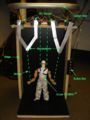
Stage Front
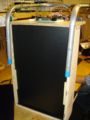
Stage Back
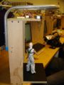
Stage Side


Six RC servos are used in this project. Four are used for the movement of the two arms, and two others are used to move the entire body. Arm movement is accomplished by incorporating a pair of 2 DOF parallel manipulators using the four servos. For each parallel manipulator, two servos placed 1.5 inches apart along the edge of the top platform provide actuation to a 5-bar linkage. Each section of the linkage is made the same length at 3 inches from the point of rotation. With this linkage geometry, the tip of the 5-bar linkage can sweep an area of the X-Y plane that is parallel to the front edge of the structure. The max region of travel forms a curved rhombus in this plane. Attached to the end tip of the 5-bar linkage is a string that is attached to the wrist of the puppet on the other end. A movement of the manipulator, therefore, generates a corresponding movement of the arm, just like an actual marionette.

The GIJoe action figure, as manufactured, featured a much stiffer arm joints than desired for our purpose. Therefore, the arm joints are drilled out and re-tied together with strings, leaving a much looser arm movement.
Two extra servos are attached behind the first row of arm manipulating servos. These servos pull strings through an opening in the middle of the platform and are attached to the puppet’s shoulders. When the strings are relaxed, both feet of the puppet contact the ground. When both strings are pulled, the puppet will look like it is jumping. When one string is pulled, one foot will lift. If correctly correlated, sideways movement of the puppet can be achieved by lifting one foot and then the other (see the “Hula Dance” routine).
To finish off the construction, black PVC sheets are placed on the back and base of the frame to give it a “stage” look, which also masks the black strings quite well. In addition, a long piece of aluminum tubing is bent into shape and mounted on the back of the structure to provide support for the curtains. After the curtains are in place, none of the swing arms or electronics can be seen, giving an effect of a freestanding, free-moving puppet.
Electrical Design
Code
This first section of code is our set up code. This is everything but the routines and main method. Our full code is here
#include <18f4520.h>
#device high_ints=TRUE        // this allows raised priority interrupts, which we need
#fuses HS,NOLVP,NOWDT,NOPROTECT
#use delay(clock=40000000)

int16 RCservo[6];        // We used 6 servos.
int RCcount;
signed int16 i = 400;
int16 j = 400;
int m = 1;
int16 k = 400;
int16 n = 0;

#INT_TIMER2       // designates that this is the routine to call when timer2 overflows
void MyInterruptRoutine() {

   if (++RCcount >= 25) RCcount = 0;         // 25mS cycle to check all servos.

   if ((RCcount & 3) == 0) {  // on the 4mS boundaries turn all the pins low
      output_low(PIN_D0);     // comment out the pins you don't want involved
      output_low(PIN_D1);
      output_low(PIN_D2);
      output_low(PIN_D3);
      output_low(PIN_D4);
      output_low(PIN_D5);

      set_timer3((int16) 60536 + RCservo[RCcount>>2]);     // yes 60536, not 65536.  Go high 4000uS (5000*0.8uS) from now, and sooner due to desired High period
   }

 }

#INT_TIMER3 fast           // "fast" allows Timer 3 to interrupt Timer 2's ISR
void InterruptTimer3() {   // this ISR is called when Timer 3 times out, to set one of the RC servo output pins high
   switch (RCcount>>2) {
      case 0:
         output_high(PIN_D0);     // This finishes setting up all our servos for use.
         break;
      case 1:
         output_high(PIN_D1);
         break;
      case 2:
         output_high(PIN_D2);
         break;
      case 3:
         output_high(PIN_D3);
         break;
      case 4:
         output_high(PIN_D4);
         break;
      case 5:
         output_high(PIN_D5);
         break;
   }
}

void servoLeft(int16 x, int16 y) {  //This routine controls the two left arm servos in the X and Y direction.
   RCservo[0] = 1700 - x + y;       //Typing servoLeft(100,0) would move the arm in the X direction 100.
   RCservo[1] = 1700 - x - y;       //It uses the two servos of the arm together to move correctly.
}

void servoRight(int16 x, int16 y) {//This is the same as above except for the right arm.
   RCservo[2] = 1700 - x + y;
   RCservo[3] = 1700 - x - y;
}

void servoXY2(int16 x, int16 y) {  //This controls the feet.  X was for one shoulder and Y was for the other.
      RCservo[4] = 1400 + x ;
      RCservo[5] = 1900 - y;
      }
void servoArm(int16 x, int16 y){   //This is another way of controlling the left arm.  Instead of moving in a
      RCservo[0] = 1700 - x ;      //specific XY direction, using servoArm let you control the two servos for the
      RCservo[1] = 1700 - y;       //left arm individually, which made some movements easier to code for.
}
void servoArm2(int16 x, int16 y){  //This is the same as above but for the right arm.
      RCservo[2] = 1700 - x ;
      RCservo[3] = 1700 - y;
}

void ZeroServos() {                 //This routine reset the servo positions back to neutral.
      servoLeft(0,0);
      servoRight(0,0);
      servoXY2(0,0);
      i = 0;
}
The next section of code are our routines. The routine showed here is our HulaHula routine.
void HulaHula(){                 //This is one of our routines, the Hula dance.  The if statements inside the
i=0;                             //while loops controlled the movement of the feet going up and down.
j=0;                             // k controlled how how each foot went and m controlled if the foot was going up
k=200;                           //or down.  i and j controlled the arm servos.  the delay_ms found in these routines
   while(i<700){                 //was to slow down the movements slightly.  this reduced the jerkyness which reduced
         servoArm(i,j);          //the swaying of the string so our movements were more controlled.
         servoArm2(i,j);
         i=i+1;
         j=j+1;
         servoXY2(k, 0);
         if(k > 200) m=2;
         if(k < 2) m = 1;
         if(m == 1) k=k+1;
         if(m == 2) k=k-1;
         delay_ms(1);
      }
   delay_ms(500);
   while(i>0){
         servoArm(i,j);
         servoArm2(i,j);
         i=i-1;
         j=j-1;
         servoXY2(k, 0);
         if(k > 200) m=2;
         if(k < 2) m = 1;
         if(m == 1) k=k+1;
         if(m == 2) k=k-1;
         delay_ms(1);
      }
   while(i<700){
         servoArm(i,j);
         servoArm2(i,j);
         i=i+1;
         j=j+1;
         servoXY2(k, 0);
         if(k > 200) m=2;
         if(k < 2) m = 1;
         if(m == 1) k=k+1;
         if(m == 2) k=k-1;
         delay_ms(1);
      }
   delay_ms(500);
   while(i>0){
         servoArm(i,j);
         servoArm2(i,j);
         i=i-1;
         j=j-1;
         servoXY2(k, 0);
         if(k > 2) m=2;
         if(k < 200) m = 1;
         if(m == 1) k=k+1;
         if(m == 2) k=k-1;
         delay_ms(1);
      }
   while(i<700){
         servoArm(-i,-j);
         servoArm2(-i,-j);
         i=i+1;
         j=j+1;
         servoXY2(0, k);
         if(k > 200) m=2;
         if(k < 2) m = 1;
         if(m == 1) k=k+1;
         if(m == 2) k=k-1;
         delay_ms(1);
      }
   delay_ms(500);
   while(i>0){
         servoArm(-i,-j);
         servoArm2(-i,-j);
         i=i-1;
         j=j-1;
         servoXY2(0, k);
         if(k > 200) m=2;
         if(k < 2) m = 1;
         if(m == 1) k=k+1;
         if(m == 2) k=k-1;
         delay_ms(1);
         }
   while(i<700){
         servoArm(-i,-j);
         servoArm2(-i,-j);
         i=i+1;
         j=j+1;
         servoXY2(0, k);
         if(k > 200) m=2;
         if(k < 2) m = 1;
         if(m == 1) k=k+1;
         if(m == 2) k=k-1;
         delay_ms(1);
      }
   delay_ms(500);
   while(i>0){
         servoArm(-i,-j);
         servoArm2(-i,-j);
         i=i-1;
         j=j-1;
         servoXY2(0, k);
         if(k > 200) m=2;
         if(k < 2) m = 1;
         if(m == 1) k=k+1;
         if(m == 2) k=k-1;
         delay_ms(1);
      }
 }
After our routines, we have our Main method.
void main() {
      setup_timer_2(T2_DIV_BY_4, 155, 16);       // clock at 16KHz; interrupt every 4*50nS * 4 * (77+1) * 16 = 1.0mS
      setup_timer_3(T3_INTERNAL | T3_DIV_BY_8); // Timer 3 is used for the High period for the RC servo signal, ticks every (4*50nS) * 4 = 0.8uS

      enable_interrupts(INT_TIMER3);
      enable_interrupts(INT_TIMER2);
      enable_interrupts(GLOBAL);

   while (TRUE) {                   //This is the while loop in our main function.  it zeros the servos and then
          ZeroServos();             //waits for a button press.  When it gets a button press it does its
          if(input(PIN_A0))         //specified routine.
         {
            leftArmPoint();
         }
         if(input(PIN_A1))
         {
            HulaHula();
            HulaHula();
         }
         if(input(PIN_A2))
         {
            Jump();
            Jump();
            Jump();
            Jump();
         }
         if(input(PIN_A3))
         {
            Conduct();
            Conduct();
            Conduct();
         }
         if(input(PIN_A4))
         {
            Move4();
            Move4();
            Move4();
            Move4();
         }


   }
}