Interfacing with a touchscreen
Original Assignment
Interface the PIC with a surplus touchscreen from the LIMS lab and display (x,y) data on an LCD screen (see, e.g., C Example: Serial LCD or C Example: Parallel Interfacing with LCDs) or a PC (e.g., matlab or hyperterminal).
Spec sheet: [1] (Use the last .pdf under Reference Materials)
Overview
The goal of the project is to interface the PIC18F4520 with the 3M EX II 7720SC capacitive touchscreen. The spec sheet is located here: [2] (Use the last .pdf under Reference Materials). In addition, when a finger makes contact with the touchscreen, the X-Y coordinates will be displayed on a JHD 162A Parallel LCD (see C Example: Parallel Interfacing with LCDs).
There are many different types of touchscreen technologies. The one used below is a capacitive touchscreen. A capactive touchscreen is usually coated in a charge storing material, such as indium tin oxide. Voltage is applied to each corner of the glass screen and electrodes are spread uniformly throughout the screen. Capactive touchscreens are only responsive to finger touch which draw current from each side of the screen proportionally. The controller will then calculate the X-Y position of the finger from the current.
Advantages of the touchscreen are high touch resolution, high image clarity, and is not affected by dirt, grease, or moisture. However it can only be activated by the touch of something conductive, such as one's finger. [3]
On this page you will find the steps to implement the touchscreen interface on your own. This includes the code, circuit diagram, and other notes about creating the interface.
Circuit
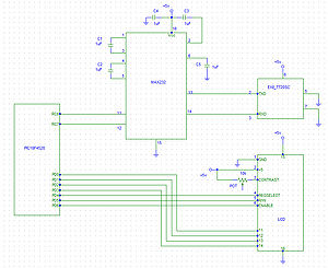
The image on the right is the circuit schematic showing the connections between all the components. An actual picture of the circuit is also shown.
The chips required for implementing this circuit are:
1) PIC 18F4520
2) MAX232N Dual EIA-232 Driver/Receiver
3) EXII 7720SC (touchscreen controller chip)
4) JHD 162A Parallel LCD
The PIC communicates with the touchscreen through the MAX232N chip. The MAX232N chip regulates the voltage of the input(RXD pin 3) and output(TXD pin 2) of the EXII 7720SC touchscreen chip(between -5V and +5V) to make it between 0 and +5V, since this is the signal range that is accepted by the PIC.
The PIC first transmits a "Format Tablet" command to the touchscreen chip, which tells the touchscreen what to transmit back to the PIC. When a finger makes contact with the touchscreen, the chip sends back a 10-byte string of hex values with the X and Y coordinates embedded in the first 5 bytes. This 10-byte string is processed by the PIC, which extracts the X and Y coordinates, converts them to int16 format, and outputs the numbers to the LCD.
The +5V supply voltages and ground in the circuit can be connected to PIC +5V and ground.
Note: When wiring the touchscreen you have a couple of options. The first option is to buy the appropriate connecting cables for the EXII 7720SC chip to interface with a PIC. If this is not a feasible option then a second option would be to take spare rainbow ribbon cable and fashion your own connecting cable. This can be down with a wire stripper and soldering. The circuit pictured here is an example of the second option.